1. Introduction
This manual provides detailed instructions for the installation, operation, and maintenance of your Generic Q67H2-AM Motherboard. This motherboard is designed to support Intel 2nd Generation Core i3, i5, and i7 processors with an LGA 1155 socket. Please read this manual thoroughly before proceeding with installation to ensure proper setup and to prevent damage to your components.
2. Safety Information
Always observe the following safety precautions:
- Disconnect power from the system before installing or removing any components.
- Wear an anti-static wrist strap to prevent electrostatic discharge (ESD) damage to sensitive components.
- Handle components by their edges; avoid touching pins or circuitry.
- Ensure proper ventilation in your computer case to prevent overheating.
- Keep liquids away from electronic components.
3. Package Contents
Verify that your package contains the following items:
- Generic Q67H2-AM Motherboard
- I/O Shield (may vary by package)
- SATA Data Cables (may vary by package)
- User Manual (this document)
4. Setup
4.1 Motherboard Layout
Familiarize yourself with the various ports and connectors on your motherboard.
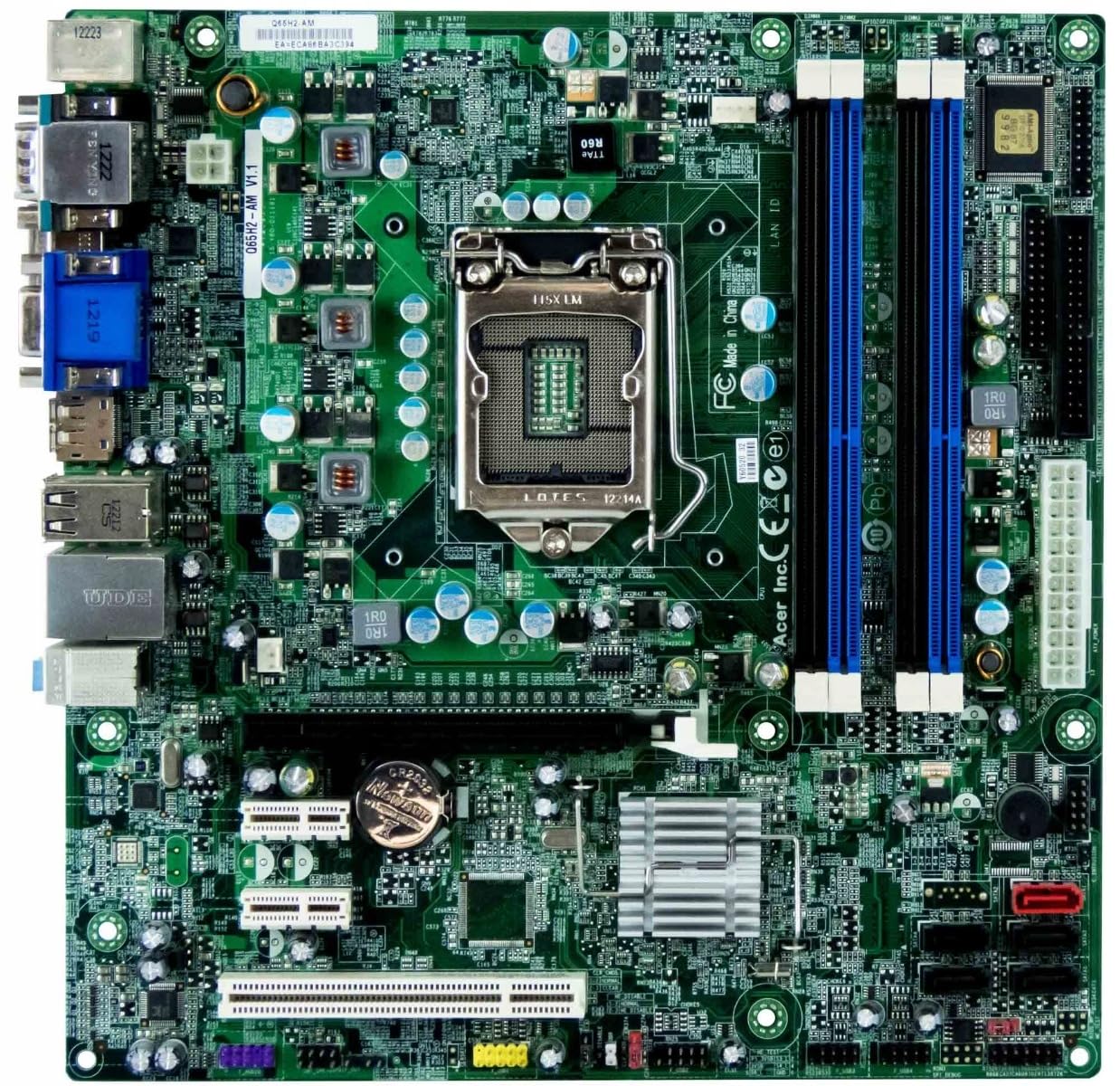
Image 1: Rear I/O ports of the Generic Q67H2-AM Motherboard. From left to right, it shows two PS/2 ports (green and purple), a serial port, a VGA port, a DVI-D port, an HDMI port (partially visible), four USB ports, an Ethernet port, and three audio jacks (light blue, lime green, pink).
The image above displays the rear input/output panel of the Q67H2-AM motherboard. Key connectors include PS/2 ports for legacy keyboards and mice, various video outputs (VGA, DVI-D, and potentially DisplayPort/HDMI), multiple USB ports for peripherals, a Gigabit Ethernet port for network connectivity, and audio jacks for sound input/output.
4.2 CPU Installation
- Locate the LGA 1155 CPU socket on the motherboard.
- Gently push down the load lever and pull it out to open the CPU socket cover.
- Carefully align the notches on your Intel 2nd Generation LGA 1155 processor with the socket. Do not force the CPU into the socket.
- Once the CPU is seated correctly, close the metal load plate and secure it with the load lever.
- Apply a thin, even layer of thermal paste to the top of the CPU (if not pre-applied to the cooler).
- Install the CPU cooler according to its manufacturer's instructions, ensuring it is securely fastened.
4.3 RAM Installation
This motherboard supports up to 16GB of DDR3 1333 MHz non-ECC, un-buffered memory across four 240-pin DIMM slots.
- Open the clips at both ends of the DIMM slot.
- Align the notch on the DDR3 memory module with the key in the DIMM slot.
- Insert the memory module firmly into the slot until the clips snap into place.
- For dual-channel operation, refer to your motherboard's specific manual for recommended slot configurations (e.g., slots 1 and 3, or 2 and 4).
4.4 Storage Device Connection
The motherboard features 2x SATAIII 6Gb/s connectors (red) and 4x SATAII 3Gb/s connectors (black).
- Connect one end of a SATA data cable to a SATA port on the motherboard.
- Connect the other end of the SATA data cable to your hard drive or SSD.
- Connect a SATA power cable from your power supply unit (PSU) to the storage device.
4.5 Power Connection
- Connect the 24-pin ATX power connector from your PSU to the corresponding header on the motherboard.
- Connect the 4-pin ATX 12V power connector (CPU power) from your PSU to the header near the CPU socket.
4.6 Expansion Card Installation
The motherboard includes 1x PCI Express x16 slot, 2x PCI Express x1 slots, and 1x PCI slot.
- Align your expansion card (e.g., graphics card, network card) with the desired slot.
- Press down firmly until the card is fully seated in the slot and the retention clip (if present) engages.
- Secure the card to the chassis with a screw.
4.7 Front Panel Connections
Connect the cables from your computer case's front panel (power button, reset button, USB ports, audio jacks, LED indicators) to the corresponding headers on the motherboard. Refer to the motherboard's silkscreen labels for correct pin assignments.
5. Operating
5.1 Initial Boot-up
After all components are installed and connected, power on your system. The system should display the BIOS/UEFI splash screen.
5.2 BIOS/UEFI Configuration
Press the designated key (usually DEL or F2) during boot-up to enter the BIOS/UEFI setup. Here you can configure boot order, system time, and other hardware settings. Save changes before exiting.
5.3 Driver Installation
After installing your operating system, install the necessary drivers for the chipset, integrated graphics, LAN, and audio. These drivers are typically available from the motherboard manufacturer's website or the chipset manufacturer (Intel).
6. Maintenance
6.1 Cleaning
Regularly clean dust from inside your computer case and off motherboard components using compressed air. Ensure the system is powered off and unplugged before cleaning.
6.2 BIOS Updates
BIOS updates can improve system stability, add support for new hardware, or fix bugs. Only update the BIOS if necessary and follow the specific instructions provided by the motherboard manufacturer carefully. Incorrect BIOS updates can render the motherboard inoperable.
7. Troubleshooting
- No Power: Ensure all power cables (24-pin ATX, 4-pin ATX 12V) are securely connected. Check the power supply unit (PSU) and wall outlet.
- No Display: Verify that the monitor is connected to the correct video output (VGA, DVI-D, DisplayPort) on the motherboard or dedicated graphics card. Reseat RAM modules and the graphics card.
- System Instability/Crashes: Check for proper CPU cooler installation and thermal paste application. Test RAM modules individually. Ensure all drivers are installed and up to date.
- Peripheral Not Detected: Ensure USB devices are connected to functional ports. Check device manager for driver issues.
- Operating System Not Booting: Verify boot order in BIOS/UEFI. Check SATA cable connections to storage devices.
If issues persist, consult a qualified technician or the product's support resources.
8. Specifications
| CPU Support | Intel 2nd Generation Core i7, Core i5, Core i3, Pentium (Dual Core) |
| Socket Type | LGA 1155 |
| Chipset | Intel Q67 |
| Video | Intel HD Graphics (Integrated) |
| Memory Slots | 4x 240-pin DDR3 DIMM Slots |
| Memory Type | Dual Channel DDR3 1333 MHz non-ECC, Un-buffered Memory |
| Max Memory | 16GB (on 64-bit Operating Systems) |
| Expansion Slots | 1x PCI Express x16, 2x PCI Express x1, 1x PCI |
| SATA Ports | 2x SATAIII 6Gb/s (red), 4x SATAII 3Gb/s (black) |
| Audio | Realtek ALC662 High Definition Audio |
| LAN | Gigabit Ethernet (RJ45) |
| Rear Panel I/O | 1x VGA, 1x DVI-D, 1x Display Port, 1x RJ45 LAN, 6x USB, 1x Serial Port, 1x Audio I/O, 2x PS/2 |
| Internal Connectors | 24-pin ATX Power, 4-pin ATX 12V Power, 4-pin CPU Fan, 3-pin Rear System Fan, Clear CMOS jumper, Battery socket, Front Panel header, Front Audio header, 2x USB headers, Floppy header |
| Form Factor | Micro-ATX |
| Dimensions (L x W x H) | 24L x 24W x 3H Centimeters |
| Weight | 750 Grams |
9. Warranty Information
This product comes with a 1-Year Warranty from the date of purchase. The warranty covers manufacturing defects under normal use. It does not cover damage caused by improper installation, misuse, accidents, unauthorized repairs, or modifications. Please retain your proof of purchase for warranty claims.
10. Support
For technical assistance or further inquiries, please refer to the retailer where the product was purchased. Ensure you have your product model number (Q67H2-AM) and proof of purchase available when seeking support.