1. Introduction
This manual provides detailed instructions for assembling and operating your DONGKER Owl LED Soldering Kit. This kit is designed for beginners and enthusiasts to learn and practice soldering skills while creating a functional and decorative LED owl light with touch control.
2. Package Contents
Before beginning assembly, please verify that all components listed below are present in your kit.
- Owl-shaped PCB (Printed Circuit Board)
- LEDs (Light Emitting Diodes)
- Resistors
- Capacitors
- Integrated Circuits (ICs)
- USB Power Cable
- Mounting Screws and Standoffs

3. Setup and Assembly
This section guides you through the soldering process. Basic soldering tools (soldering iron, solder, desoldering wick/pump, safety glasses) are required and not included.
3.1 Component Identification
Familiarize yourself with the different electronic components. The PCB is clearly marked to indicate where each component should be placed. Pay close attention to the markings for correct orientation.

3.2 Soldering Process
- Prepare Your Workspace: Ensure a well-ventilated area, clear of flammable materials. Wear safety glasses to protect your eyes.
- Identify Components: Match each component to its designated spot on the PCB using the silkscreen markings. Pay attention to polarity for LEDs, diodes, and electrolytic capacitors. The longer leg of an LED is typically positive (+).
- Solder Smallest Components First: Begin with resistors, then diodes, smaller capacitors, and finally the integrated circuits. This approach makes soldering easier by preventing larger components from obstructing access.
- Solder LEDs: Carefully solder each LED into its position. Ensure correct polarity.
- Solder USB Port: Attach the USB power port to the PCB.
- Inspect Solder Joints: After soldering each component, visually inspect the joints for proper connection. Look for shiny, cone-shaped joints. Avoid cold joints (dull, lumpy) or solder bridges (solder connecting two adjacent pads).

3.3 Final Assembly
Once all components are soldered and inspected, attach the included standoffs and screws to secure the PCB and provide stability for the finished owl light.
4. Operating Instructions
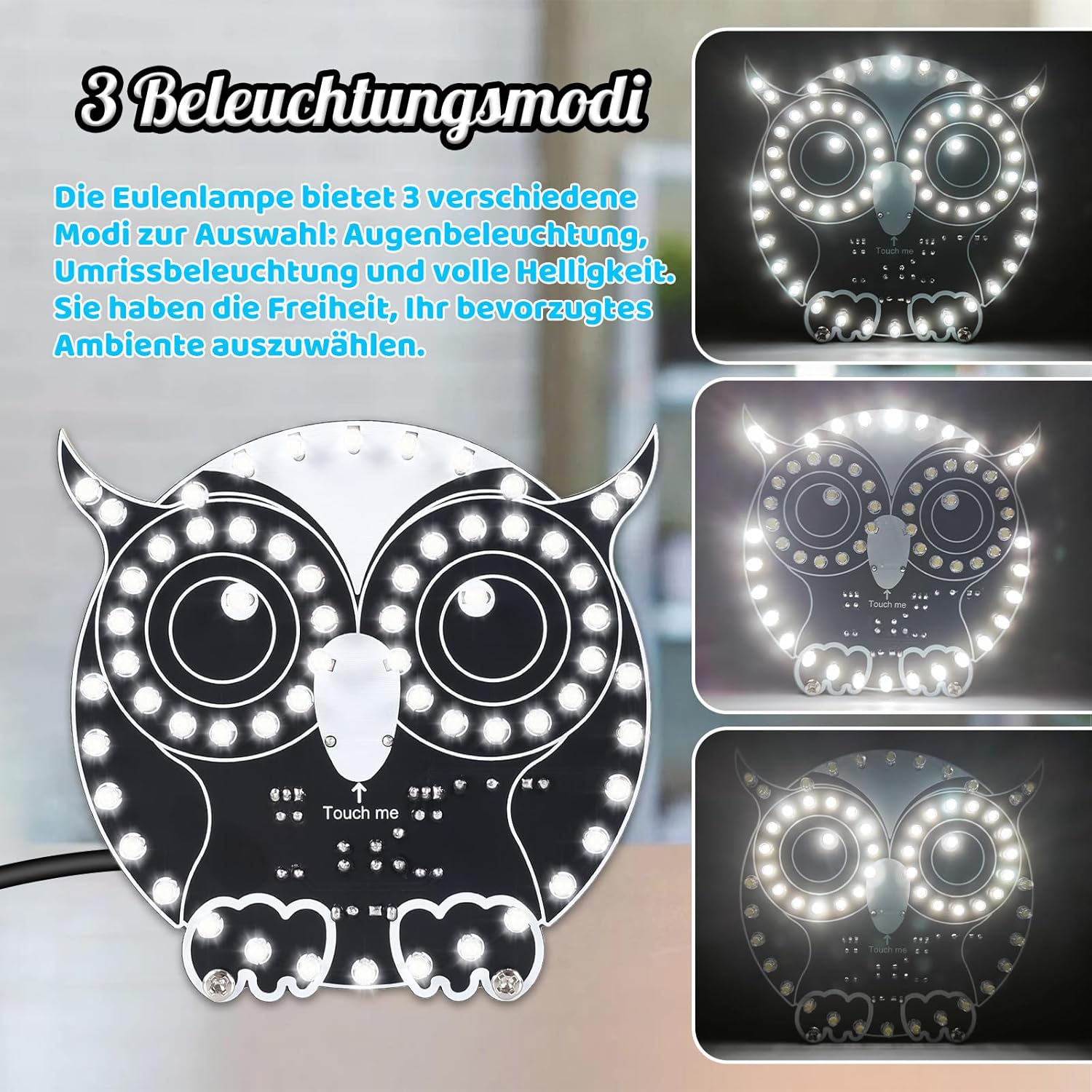
The DONGKER Owl LED light features touch control for mode selection and brightness adjustment.
4.1 Powering On
Connect the provided USB power cable to the USB port on the owl light and to a 5V DC power source (e.g., USB wall adapter, computer USB port).

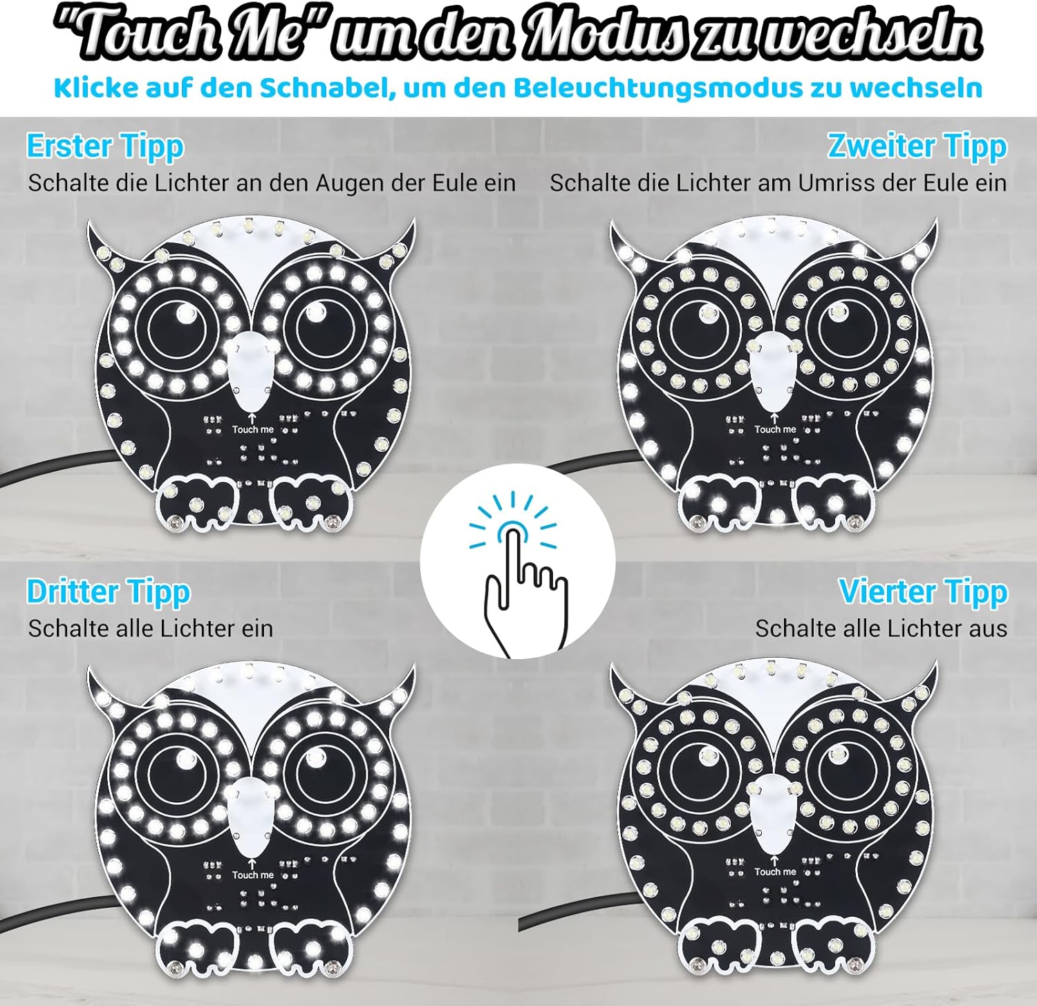
4.2 Changing LED Modes
The owl light offers three distinct LED modes. To cycle through these modes, lightly tap the "Touch me" area located on the owl's beak.
- First Tap: Activates the eye lights only.
- Second Tap: Activates the outline lights.
- Third Tap: Activates all lights for full brightness.
- Fourth Tap: Turns off all lights.
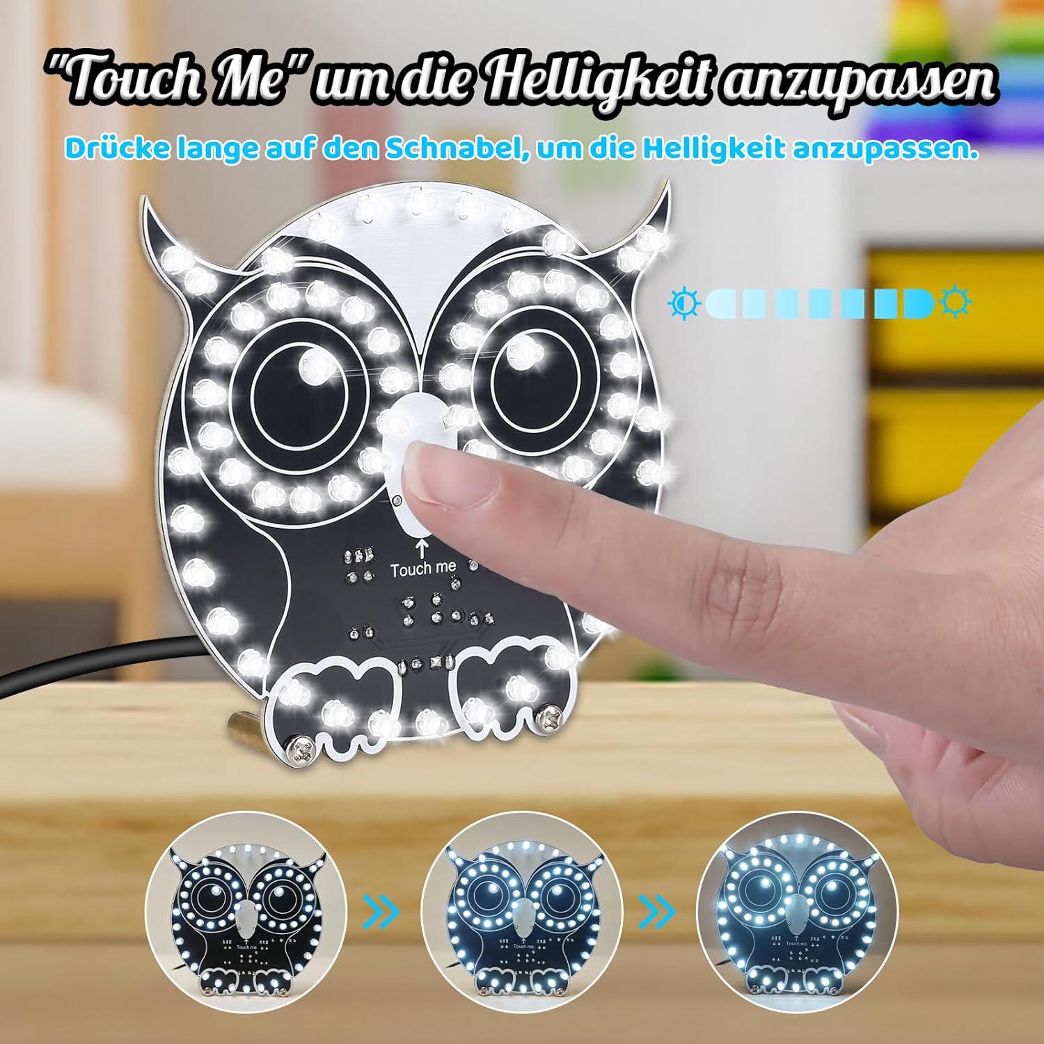

4.3 Adjusting Brightness
To adjust the brightness, press and hold your finger on the "Touch me" area. The brightness will gradually increase or decrease. Release your finger when the desired brightness level is reached.

5. Maintenance
To ensure the longevity and proper functioning of your DONGKER Owl LED light, follow these simple maintenance guidelines:
- Cleaning: Gently wipe the PCB and LEDs with a soft, dry cloth. Avoid using liquids or abrasive cleaners, which can damage electronic components.
- Storage: Store the assembled kit in a dry, dust-free environment when not in use to prevent component degradation.
- Handling: Handle the circuit board with care to avoid bending or damaging components and solder joints.
6. Troubleshooting
If you encounter issues with your DONGKER Owl LED light, refer to the following common problems and solutions:
- LEDs Not Lighting Up:
- Check power connection: Ensure the USB cable is securely connected to a working 5V power source.
- Inspect solder joints: Look for any cold joints (dull, lumpy) or solder bridges that might prevent electrical contact. Re-solder as necessary.
- Verify LED polarity: Ensure all LEDs are soldered with the correct polarity. Incorrect polarity will prevent LEDs from lighting.
- Check for short circuits: Examine the PCB for any accidental solder bridges between traces or component leads.
- Inconsistent Touch Response:
- Ensure the "Touch me" area is clean and dry. Moisture or dirt can interfere with touch detection.
- Verify the touch sensor components are correctly soldered and not damaged.
- Only Some LEDs Light Up:
- This often indicates a faulty solder joint or incorrect polarity for the unlit LEDs. Re-inspect and correct the affected LEDs.
If problems persist after attempting these solutions, please contact DONGKER customer support for further assistance.
7. Specifications
| Feature | Detail |
|---|---|
| Model Number | GY21488-1-KTH |
| Manufacturer | DONGKER |
| Power Type | DC 5V (via USB) |
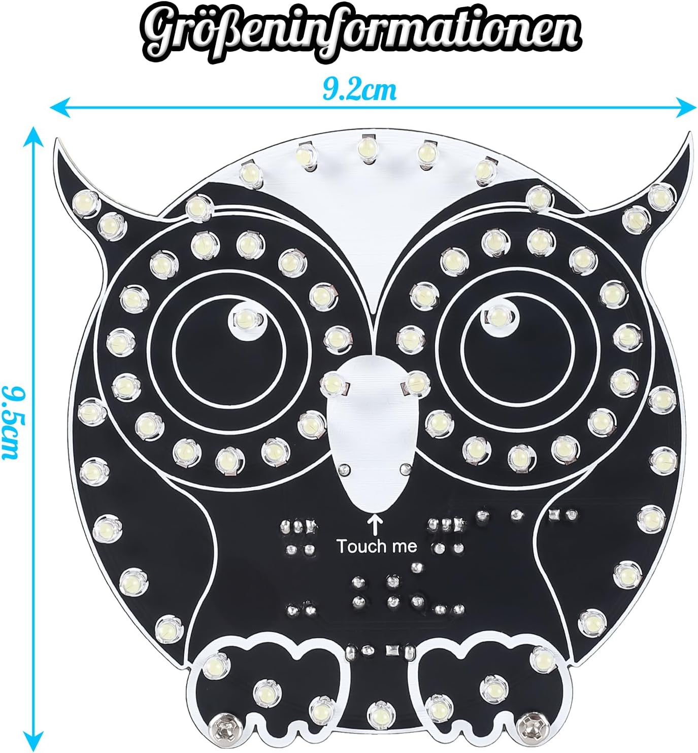
| Package Dimensions | 14.1 x 11.4 x 1.6 cm |
| Weight | 60 grams |
| Included Components | PCB, LEDs, Resistors, Capacitors, ICs, USB Cable |
| Batteries Required | No |
| Spare Parts Availability | 1 Year |

8. Warranty and Support
DONGKER is committed to providing quality products. While this is a DIY kit, we offer support for any questions you may have during assembly or operation.
- Support: If you have questions or require assistance, please contact DONGKER customer service through the retailer where you purchased the product.
- Spare Parts: Spare parts are available for 1 year from the date of purchase.