KYKYK MPPT 60A Solar Charge Controller
KYKYK MPPT 60A Solar Charge Controller User Manual
Model: MPPT 60A Solar Charge Controller
1. Introduction
This manual provides essential instructions for the safe and efficient operation of your KYKYK MPPT 60A Solar Charge Controller. This device is designed to optimize power harvesting from your solar panels and manage battery charging for 12V, 24V, 36V, and 48V systems. It features Maximum Power Point Tracking (MPPT) technology, which significantly increases charging efficiency compared to conventional controllers.
The controller incorporates multiple protection measures to safeguard your battery pack and solar system components. Please read this manual thoroughly before installation and operation.

Figure 1: Front view of the KYKYK MPPT 60A Solar Charge Controller, showing the LCD display and control buttons.
2. Safety Information
Please observe the following safety precautions during installation and operation:
- Ensure all connections are secure and correct polarity is maintained to prevent damage to the controller and other components.
- Always disconnect power from solar panels and batteries before installing or servicing the controller.
- Install the controller in a well-ventilated area, away from flammable materials and direct sunlight.
- Do not attempt to disassemble or repair the controller yourself. Contact qualified personnel for service.
- The controller is designed for specific voltage systems (12V, 24V, 36V, 48V). Ensure your system voltage matches the controller's setting.
- This device handles high voltages and currents. Exercise extreme caution to avoid electrical shock.

Figure 2: Diagram illustrating the various protection features of the controller, including short circuit, overcurrent, reverse polarity, overload, low voltage, and overheat protection.
3. Product Features
The KYKYK MPPT 60A Solar Charge Controller offers advanced features for optimal solar power management:
- Maximum Power Point Tracking (MPPT): Automatically traces the maximum power point of solar panels, increasing charging efficiency by 10% to 30% compared to non-MPPT controllers.
- Comprehensive Protection: Includes short circuit, overcurrent, reverse polarity, overload, low voltage, and overheat protections to safeguard the battery and system.
- High Efficiency: Charging efficiency up to 99%.
- Intelligent Operation: Easy installation and setup with full intelligence for automated system management.
- Effective Heat Dissipation: Utilizes a metal housing and integrated fan to improve heat dissipation and maintain optimal performance.
- Detailed LCD Display: Provides real-time system information and status updates.
- Multi-Voltage Compatibility: Supports 12V, 24V, 36V, and 48V battery systems.
4. Product Overview and Components
Familiarize yourself with the main components of your solar charge controller:
Figure 3: Overview of the controller's external features, including the LCD display, control buttons (A, B, C, D), Solar Panel Terminal, Battery Terminal, and Load Terminal.
- LCD Display: Shows real-time system parameters such as PV input voltage, battery voltage, load output, charging status, and error codes.
- Control Buttons (A, B, C, D): Used for navigating menus, adjusting settings, and resetting the device. Button D also serves as a 5-second reset function.
- Solar Panel Terminal: Connects to your solar panel array.
- Battery Terminal: Connects to your battery bank.
- Load Terminal: Connects to your DC loads.

Figure 4: Internal view of the controller, highlighting key components such as capacitance and copper coil transformers, indicative of robust construction.
5. Setup and Installation
Follow these steps for proper installation of your solar charge controller:
- Mounting: Mount the controller vertically on a non-flammable surface in a cool, dry, and well-ventilated indoor location. Ensure adequate clearance around the unit for heat dissipation.
- Wiring Sequence:
- Connect the battery to the battery terminals (+ and -). Ensure correct polarity.
- Connect the DC load to the load terminals (+ and -). Ensure correct polarity.
- Connect the solar panels to the PV input terminals (+ and -). Ensure correct polarity.
Important: Always connect the battery first, then the load, and finally the solar panels. Disconnect in the reverse order.
- System Voltage Setting: The controller automatically detects 12V, 24V, 36V, or 48V battery systems. Verify the detected voltage on the LCD display.
- Solar Panel Voltage Requirements:
- For a 12V system (battery 12V), the solar panel open circuit voltage (PV Voc) should be in the range of 18V to 72V. Max PV Input Power: 720W.
- For a 24V system (battery 24V), the solar panel open circuit voltage (PV Voc) should be in the range of 36V to 96V. Max PV Input Power: 1440W.
- For a 36V system (battery 36V), the solar panel open circuit voltage (PV Voc) should be in the range of 54V to 120V. Max PV Input Power: 2100W.
- For a 48V system (battery 48V), the solar panel open circuit voltage (PV Voc) should be in the range of 72V to 144V. Max PV Input Power: 2800W.
- Parallel Connection: For higher current requirements, two 60A controllers can be connected in parallel to achieve a total MPPT 120A capacity.
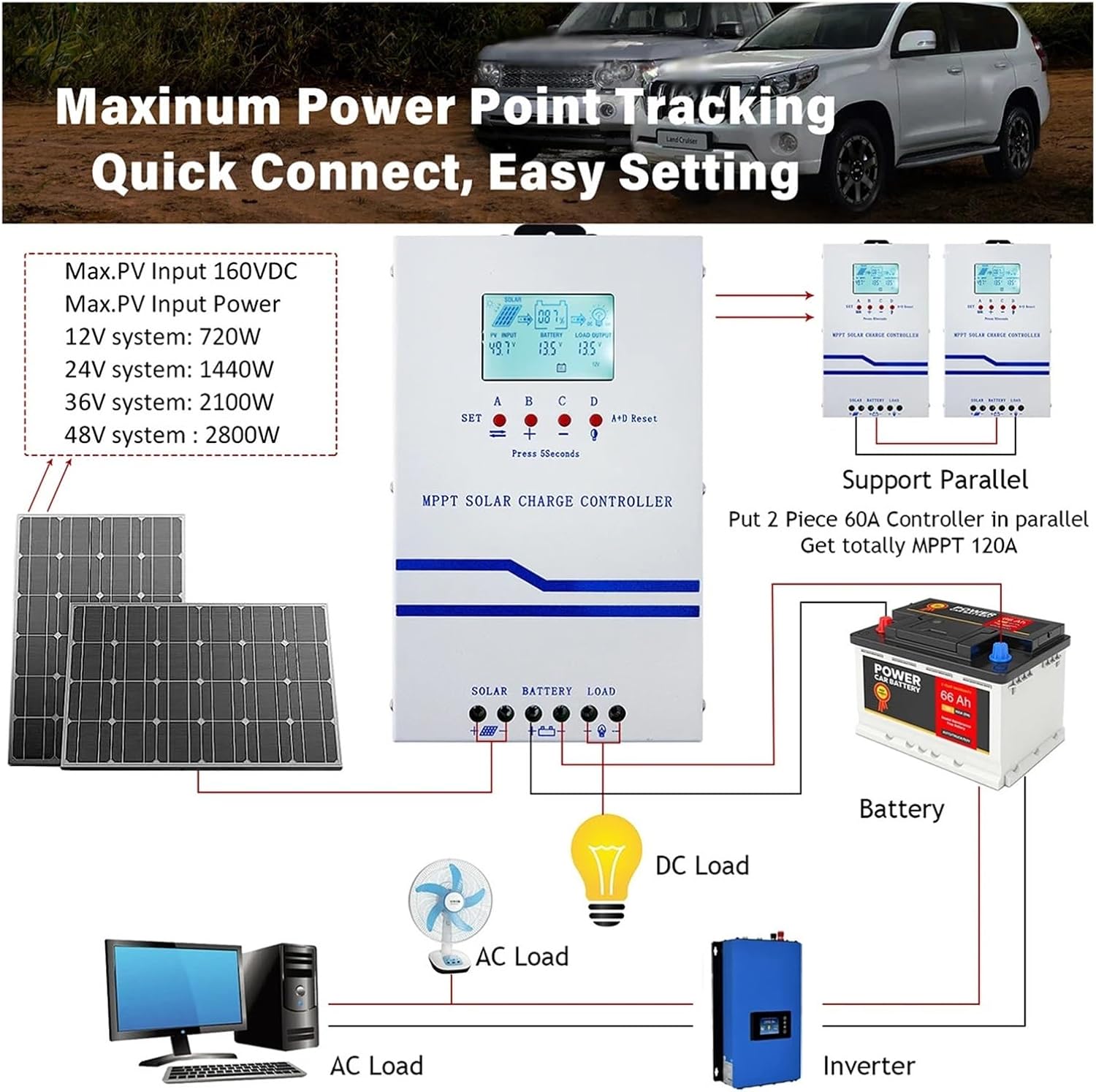
Figure 5: Detailed wiring diagram showing connections for solar panels, battery, and DC load. It also illustrates how to connect an inverter to the battery and the option for parallel controller setup.

Figure 6: Example application diagram demonstrating the integration of the MPPT solar charge controller within a typical home solar power system, connecting solar panels to batteries and powering various household appliances.
6. Operating Instructions
The LCD display provides real-time information about your solar system. Use the control buttons to navigate and adjust settings.
6.1 LCD Display Interpretation

Figure 7: Detailed breakdown of the LCD display icons and parameters, explaining their meanings and values.
| Symbol/Abbreviation | Meaning |
|---|---|
| V | Voltage |
| A | Electric current |
| ! (Fault/Error icon) | Fault or Error indication |
| °C | Internal temperature |
| % | Battery capacity percentage |
| PV INPUT | Solar panel input parameters (Voltage, Current, Power, KWH) |
| BATTERY | Battery parameters (Voltage, Current, Power, KWH) |
| LOAD OUTPUT | Load output parameters (Voltage, Current, Power, KWH) |
| [SET] | Setting mode |
| [LOAD TIME] | Load timer setting |
| [FAULT] | Fault history/details |
| USE / FLD / GEL / SLD / Li | Battery type selection (User-defined, Flooded, Gel, Sealed, Lithium) |
| fLd 13.8V | Full voltage (PV OFF = FULL VOLTAGE) - Fully charged battery voltage |
| LPU 12.6V | Load ON - Turn on the load again after under-voltage charging |
| LdU 10.6V | Load OFF - Battery undervoltage shutdown load |
| Total KWH | Cumulative power of solar power generation |
6.2 Button Functions
- SET (Button A): Enter/exit setting mode, confirm selections.
- + (Button B): Increase value, navigate forward through menus.
- - (Button C): Decrease value, navigate backward through menus.
- A+D Reset (Button D): Press for 5 seconds to reset the controller.
7. Maintenance
Regular maintenance ensures the longevity and optimal performance of your solar charge controller:
- Cleanliness: Keep the controller clean and free from dust and debris. Use a dry cloth for cleaning.
- Connections: Periodically check all wiring connections for tightness and corrosion. Loose connections can cause overheating and damage.
- Ventilation: Ensure the ventilation openings are not blocked to allow proper airflow for cooling.
- Environmental Conditions: Verify that the operating environment remains within the specified temperature and humidity ranges.
- System Monitoring: Regularly monitor the LCD display for any error codes or unusual readings.
8. Troubleshooting
This section addresses common questions and issues you might encounter:
- Q: Can an inverter be connected to the controller's load port?
A: No, the inverter should always be connected directly to the battery terminals, not the controller's load port. Inverters draw high instantaneous current which can overload the controller's load output.
- Q: Can a DC water pump be connected to the controller's load port?
A: Connecting a DC water pump to the load port is generally not recommended due to the high instantaneous current during startup, which can cause an overload. However, a DC pump of less than 200 watts might be attempted with caution, but direct battery connection is safer for higher power pumps.
- Q: What if the display shows an error code?
A: Refer to the LCD display interpretation (Figure 7) for general fault indications. If a specific error code is displayed, consult the full product documentation or contact customer support for detailed troubleshooting steps.
- Q: The battery is not charging. What should I check?
A:
- Verify solar panel connections and polarity.
- Check battery connections and polarity.
- Ensure solar panel open circuit voltage (PV Voc) is within the specified range for your system voltage (e.g., 18V-72V for 12V system).
- Check for sufficient sunlight on the solar panels.
- Inspect for any visible damage to cables or the controller.
9. Specifications
| Parameter | Value |
|---|---|
| Brand | KYKYK |
| Model | MPPT 60A Solar Charge Controller |
| System Voltage | 12V / 24V / 36V / 48V Auto Recognition |
| Max PV Input Voltage | 160VDC |
| Max PV Input Power (12V System) | 720W |
| Max PV Input Power (24V System) | 1440W |
| Max PV Input Power (36V System) | 2100W |
| Max PV Input Power (48V System) | 2800W |
| Rated Charge Current | 60A |
| Item Weight | 4.41 pounds |
| Package Dimensions | 1.18 x 0.79 x 0.39 inches |
| Manufacturer | KYKYK |
10. Warranty and Support
For warranty information and technical support, please refer to the documentation included with your product or contact KYKYK customer service. Ensure you have your product model and purchase details available when seeking support.
For further assistance, please visit the official KYKYK website or contact your retailer.