
1. Introduction
This manual provides detailed instructions for the installation, operation, maintenance, and troubleshooting of the Generic M3260 Dual-Channel Motherboard. This motherboard is specifically designed for use in NF5270M4 server systems, offering robust performance and reliability for demanding server environments. Please read this manual thoroughly before proceeding with any installation or operation to ensure proper functionality and safety.
2. Safety Information
Always observe the following safety precautions to prevent damage to the motherboard and injury to yourself:
- Electrostatic Discharge (ESD) Prevention: Always wear an anti-static wrist strap or frequently touch a grounded metal object before handling the motherboard or any components. ESD can severely damage electronic components.
- Power Disconnection: Ensure the server system is completely powered off and disconnected from the AC power source before installing or removing any components.
- Component Handling: Handle the motherboard by its edges. Avoid touching integrated circuits, connectors, or other sensitive components directly.
- Ventilation: Ensure adequate ventilation within the server chassis to prevent overheating.
- Professional Installation: If you are unfamiliar with server hardware installation, seek assistance from a qualified technician.
3. Package Contents
Verify that all items are present in the package. If any item is missing or damaged, contact your vendor immediately.
- Generic M3260 Dual-Channel Motherboard (YZMB-00609-101 / YPCB-00609-1P1)
- User Manual (this document)
- SATA Data Cables (quantity may vary)
- I/O Shield
- Driver CD/USB (if applicable)
4. Product Overview
The M3260 motherboard features a dual-channel architecture designed to support two CPUs, providing high processing power for server applications. It includes multiple DIMM slots for extensive memory capacity and numerous PCIe slots for expansion cards.
4.1 Motherboard Layout and Key Components
Refer to the images below for a visual guide to the motherboard's layout and key components.

Figure 1: M3260 Motherboard Component Detail. This image provides a detailed view of the motherboard's central area, highlighting the CPU socket, multiple RAM (DIMM) slots, and PCIe expansion slots. Key labels visible include the model number M3260, part numbers YZMB-00609-101 and YPCB-00609-1P1, and a CMOS clear jumper labeled J46. CLR CMOS. Other connectors such as LAN_EN, TCM, and 80 PORT are also visible, along with the CMOS battery (B50).
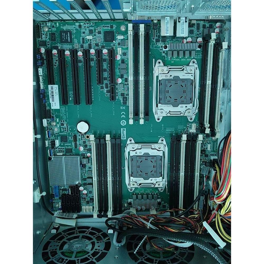
Figure 2: M3260 Motherboard Installed in Chassis. This image displays the M3260 motherboard fully installed within a server chassis. It clearly shows the layout with two CPU sockets, surrounded by numerous DIMM slots for memory modules, and a comprehensive array of PCIe expansion slots. Various power and data cables are connected, illustrating a typical server configuration.
4.2 Connectors and Headers
- CPU Sockets: Two sockets for compatible server processors.
- DIMM Slots: Multiple slots for DDR4 ECC Registered memory modules.
- PCIe Slots: Various PCIe x16, x8, and x4 slots for expansion cards (e.g., network cards, storage controllers).
- SATA Ports: Connectors for SATA storage devices.
- USB Headers: Internal headers for front panel USB ports.
- Power Connectors: ATX 24-pin and EPS 8-pin (or similar) power connectors.
- CMOS Clear Jumper (J46. CLR CMOS): Used to reset BIOS settings to default.
- LAN_EN Header: Likely for enabling/disabling LAN functionality.
- TCM Header: Trusted Platform Module (TPM) header for security features.
- 80 PORT Header: Diagnostic POST code display header.
5. Setup and Installation
Follow these steps carefully for proper installation of the M3260 motherboard into your NF5270M4 server chassis.
5.1 Pre-Installation Checklist
- Ensure you have all necessary components: CPUs, CPU coolers, RAM modules, storage drives, power supply, and server chassis.
- Prepare a clean, static-free workspace.
- Gather appropriate tools: Phillips head screwdriver, anti-static wrist strap.
5.2 Motherboard Installation
- Install the I/O shield into the server chassis's rear panel opening.
- Carefully align the motherboard with the standoffs in the chassis.
- Secure the motherboard to the chassis using screws, ensuring it is firmly seated.
5.3 CPU Installation
- Open the CPU socket retention mechanism.
- Carefully place the CPU into the socket, aligning the gold triangle on the CPU with the corresponding mark on the socket. Do not force the CPU.
- Close the retention mechanism to secure the CPU.
- Apply thermal paste to the CPU (if not pre-applied to the cooler).
- Install the CPU cooler according to its manufacturer's instructions, ensuring proper contact and secure mounting. Connect the CPU fan cable to the appropriate header on the motherboard. Repeat for the second CPU.
5.4 RAM (DIMM) Installation
- Open the clips at both ends of the DIMM slots.
- Align the notch on the RAM module with the key in the DIMM slot.
- Press down firmly on both ends of the RAM module until the clips snap into place.
- Refer to the motherboard's specific memory population guidelines for optimal performance.
5.5 PCIe Card Installation
- Remove the appropriate expansion slot cover from the chassis.
- Align the PCIe card with the desired PCIe slot and press down firmly until it is fully seated.
- Secure the card with a screw or retention clip.
5.6 Cable Connections
- Connect the main 24-pin ATX power cable and the 8-pin EPS CPU power cables from the power supply to the motherboard.
- Connect SATA data cables from storage drives to the SATA ports on the motherboard.
- Connect front panel headers (power button, reset button, USB ports, audio jacks, status LEDs) to their respective headers on the motherboard. Refer to the motherboard's silkscreen labels for correct orientation.
- Connect any additional power cables required for PCIe cards or other components.
6. Operating Instructions
6.1 Initial Boot-Up
- After all components are installed and cables connected, connect the server to AC power.
- Press the power button on the server chassis.
- Observe the POST (Power-On Self-Test) process. If a display is connected, you should see the BIOS/UEFI splash screen.
- If the system fails to boot, refer to the Troubleshooting section.
6.2 BIOS/UEFI Setup
To enter the BIOS/UEFI setup utility, press the designated key (commonly DEL, F2, or F10) during the POST process. Within the BIOS/UEFI, you can configure various system settings, including:
- Boot order
- Date and time
- SATA mode (AHCI/RAID)
- CPU and memory settings
- Fan speed control
Save changes before exiting the BIOS/UEFI setup.
6.3 Operating System Installation
Once the BIOS/UEFI is configured, you can proceed with installing your preferred server operating system. Boot from your OS installation media (USB drive or optical disc) and follow the on-screen instructions.
7. Maintenance
7.1 Cleaning
Regularly clean the interior of the server chassis to prevent dust buildup, which can impede airflow and lead to overheating. Use compressed air to remove dust from fans, heatsinks, and motherboard components. Ensure the system is powered off and unplugged before cleaning.
7.2 BIOS Updates
Periodically check the manufacturer's website for BIOS/UEFI updates. Updates can provide improved compatibility, stability, and new features. Follow the specific instructions provided with the BIOS update utility carefully to avoid damaging the motherboard.
7.3 CMOS Battery Replacement
The CMOS battery (labeled B50 in Figure 1) powers the real-time clock and stores BIOS settings when the system is off. If the system consistently loses time or BIOS settings, the CMOS battery may need replacement. Use a standard CR2032 coin cell battery. Ensure the system is powered off and unplugged before replacing the battery.
8. Troubleshooting
This section provides solutions to common issues you might encounter.
8.1 No Power / No Boot
- Check Power Connections: Ensure all power cables (24-pin ATX, 8-pin EPS) are securely connected to the motherboard and power supply.
- Power Supply: Verify the power supply is functional and switched on.
- Front Panel Headers: Double-check the power button connection to the motherboard.
- Minimum Configuration: Try booting with only essential components (one CPU, one RAM stick, no expansion cards) to isolate the issue.
8.2 No Display / POST Errors
- RAM: Reseat all RAM modules. Ensure they are installed in the correct slots according to the motherboard's manual. Try booting with one RAM stick at a time.
- CPU: Ensure CPUs are correctly seated and CPU power cables are connected.
- Graphics Card: If using a discrete graphics card, ensure it is properly seated in its PCIe slot and has adequate power.
- Diagnostic LEDs/POST Codes: If the motherboard has diagnostic LEDs or a POST code display (e.g., via the 80 PORT header), consult the motherboard's specific documentation for error code meanings.
8.3 Resetting BIOS to Default (Clear CMOS)
If you encounter system instability or cannot access the BIOS after making changes, you may need to clear the CMOS. This will reset all BIOS settings to their factory defaults.
- Power off the server and unplug it from the AC outlet.
- Locate the CMOS clear jumper (labeled J46. CLR CMOS in Figure 1).
- Move the jumper cap from its default position (e.g., pins 1-2) to the clear position (e.g., pins 2-3) for 5-10 seconds.
- Return the jumper cap to its default position.
- Plug in the server and power it on.
9. Specifications
| Feature | Specification |
|---|---|
| Model | M3260 |
| Part Numbers | YZMB-00609-101, YPCB-00609-1P1 |
| Compatibility | NF5270M4 Server Systems |
| CPU Sockets | Dual (LGA type, specific socket type depends on CPU generation for NF5270M4) |
| Memory Type | DDR4 ECC Registered DIMM (RDIMM) |
| Memory Slots | Multiple DIMM slots (refer to Figure 2 for visual representation) |
| Expansion Slots | Multiple PCIe slots (x16, x8, x4) |
| Storage Ports | SATA ports |
| Form Factor | Proprietary Server Motherboard (designed for NF5270M4) |
10. Warranty and Support
This Generic M3260 Motherboard is covered by a standard manufacturer's warranty. Please refer to the warranty card included with your purchase or contact your vendor for specific warranty terms and conditions. For technical support, troubleshooting assistance beyond this manual, or to inquire about replacement parts, please contact your product vendor or the manufacturer's support channels.


