1. Introduction
This user manual provides essential information for the safe and efficient operation of the ESXSWYDR VFD-M Series Frequency Inverter. The VFD-M series is a Sensorless Vector Micro AC Motor Drive designed for various industrial applications, offering precise control over AC motors. Please read this manual thoroughly before installation, operation, or maintenance to ensure proper usage and prevent potential hazards.

Figure 1.1: Front panel of the VFD-M Series Frequency Inverter, showing the digital display, control buttons (MODE, RUN, ENTER, STOP/RESET), and a rotary frequency adjustment knob. A warning label is visible at the bottom.
2. Safety Information
Important Safety Instructions: Always observe the following safety precautions to prevent personal injury or damage to the equipment. Failure to comply with these instructions may result in severe injury or death.
- Electrical Shock Hazard: This device operates with high voltage. Ensure power is disconnected before any installation, wiring, or maintenance. Wait at least 10 minutes after removing power before servicing to allow capacitors to discharge.
- Qualified Personnel: Installation, wiring, and maintenance must be performed by qualified electrical personnel only.
- Proper Grounding: Ensure the inverter is properly grounded according to local and national electrical codes.
- Environmental Conditions: Do not operate the inverter in environments with excessive dust, corrosive gases, flammable materials, or direct sunlight. Ensure adequate ventilation.
- Overload Protection: Do not exceed the rated current or power specifications of the inverter and connected motor.
- Emergency Stop: Always ensure an accessible emergency stop mechanism is in place for the motor system.

Figure 2.1: Two VFD-M Series units, illustrating the compact form factor and potential size variations within the series, each featuring a digital keypad and control knob.
3. Product Features
The VFD-M Series Frequency Inverter offers a range of features designed for precise and reliable motor control:
- Sensorless Vector Control: Provides excellent speed regulation and torque response without the need for an encoder.
- Micro AC Motor Drive: Compact design suitable for various applications where space is a consideration.
- Wide Voltage Range: Available in 220V and 380V models, supporting both single-phase and three-phase input configurations depending on the specific model and power rating.
- Adjustable Frequency Output: Capable of outputting frequencies from 0.1 Hz to 400 Hz.
- Digital Keypad Control: Integrated digital display and buttons for easy parameter setting and operation.
- Built-in Protections: Includes overload endurance (150% of rated current for 1 minute), stall prevention, and DC injection braking capabilities.
- V/F Pattern Control: Adjustable Voltage/Frequency pattern for optimized motor performance.
4. Setup and Installation
Proper installation is crucial for the performance and longevity of the VFD-M Series inverter. Follow these general guidelines:
- Unpacking: Carefully remove the inverter from its packaging. Inspect for any signs of damage during transit.
- Mounting: Mount the inverter vertically on a stable, non-flammable surface, ensuring adequate clearance for ventilation. Avoid direct sunlight and heat sources.
- Wiring - Power Input: Connect the main power supply to the designated input terminals (R/L1, S/L2, T/L3 for 3-phase; L1, L2 for 1-phase). Ensure the voltage matches the inverter's rating (e.g., 220V or 380V).
- Wiring - Motor Output: Connect the motor leads to the output terminals (U, V, W). Ensure correct phase sequence for desired motor rotation.
- Wiring - Grounding: Connect the ground terminal of the inverter to a reliable earth ground.
- Control Wiring (Optional): If using external control signals (e.g., start/stop, speed reference, fault relay), connect them to the control terminals as per the detailed wiring diagram in the full product manual.
- Initial Power-Up: After all connections are secure and verified, apply power to the inverter. Observe the digital display for any error codes.
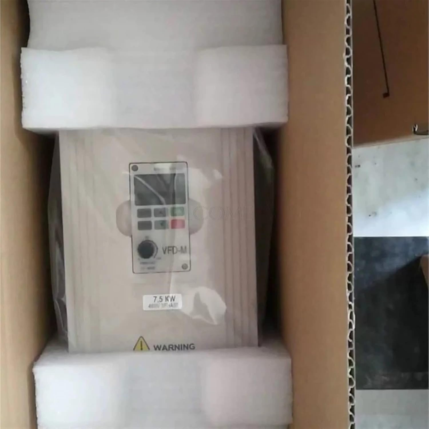
Figure 4.1: The VFD-M Series inverter shown within its protective packaging, indicating careful handling during unboxing and installation.
5. Operating Instructions
The VFD-M Series inverter features an intuitive digital keypad for operation and parameter adjustment.
5.1. Keypad Functions
- MODE: Used to switch between display modes (e.g., output frequency, output current) and to enter/exit parameter setting mode.
- RUN: Starts the motor.
- STOP/RESET: Stops the motor and clears any active fault conditions.
- ENTER: Confirms parameter settings or enters sub-menus.
- Up/Down Arrows (▲/▼): Used to navigate through parameters or adjust values.
- Rotary Knob (VFD-M): Directly adjusts the output frequency in operation mode.
5.2. Basic Operation Steps
- Power On: Apply power to the inverter. The digital display will illuminate.
- Set Frequency: In operation mode, use the rotary knob to set the desired output frequency. Alternatively, use the MODE button to enter parameter setting mode and adjust frequency-related parameters.
- Start Motor: Press the RUN button. The motor will accelerate to the set frequency.
- Stop Motor: Press the STOP/RESET button. The motor will decelerate and stop.
- Parameter Adjustment: To change advanced settings (e.g., acceleration/deceleration time, motor parameters), press the MODE button to enter parameter setting mode. Use the arrow keys to navigate and ENTER to select/confirm. Refer to the detailed parameter list in the complete manual for specific codes and ranges.
6. Specifications
The VFD-M Series offers various models with different voltage and power ratings. Below are general and specific electrical specifications.
6.1. 230V Class Specifications
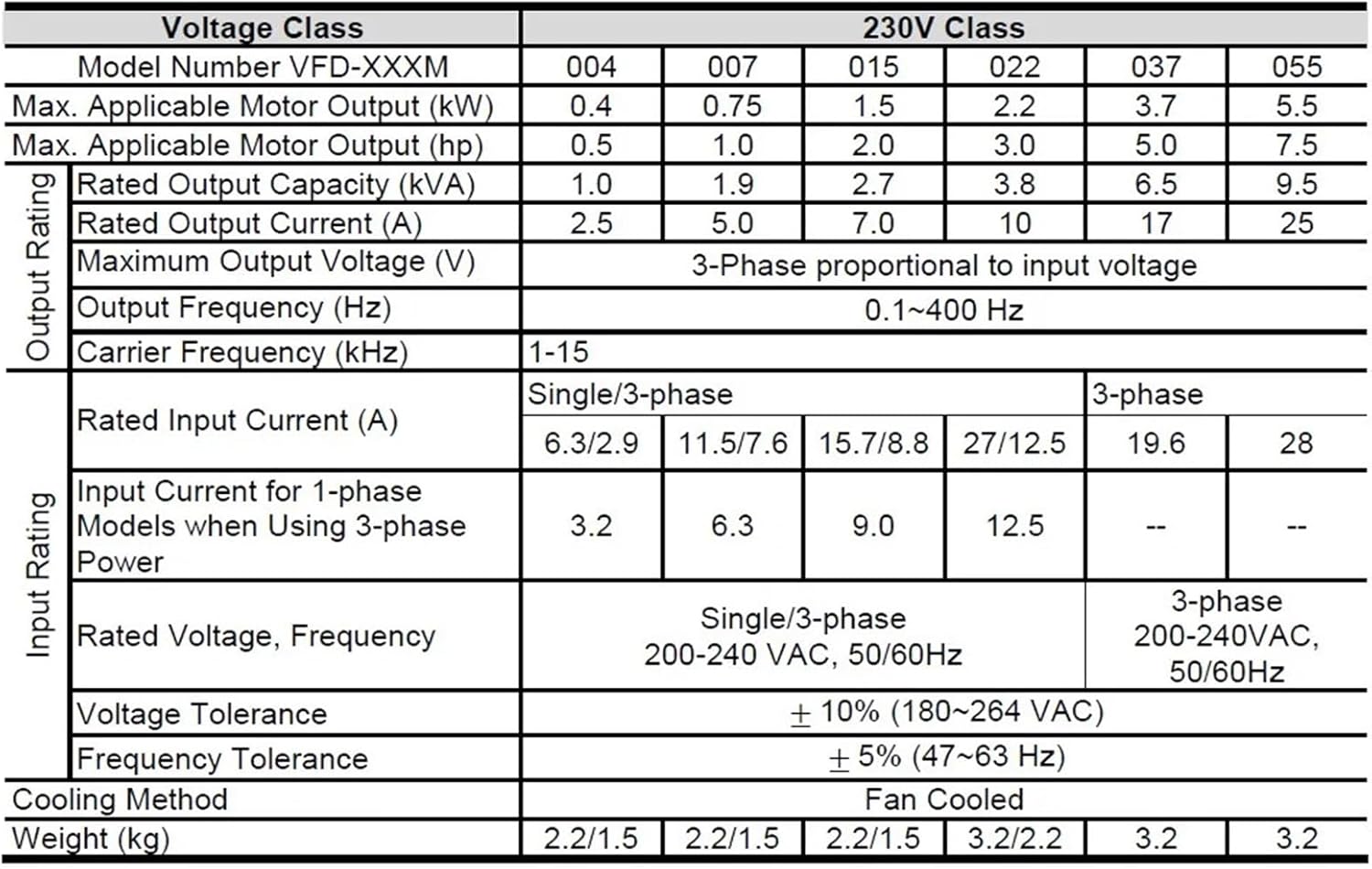
Figure 6.1: Detailed electrical specifications for VFD-M Series models operating in the 230V class, covering various power ratings from 0.4kW to 5.5kW.
| Voltage Class | 230V Class | ||||||
|---|---|---|---|---|---|---|---|
| Model Number VFD-XXXM | 004 | 007 | 015 | 022 | 037 | 055 | |
| Max. Applicable Motor Output (kW) | 0.4 | 0.75 | 1.5 | 2.2 | 3.7 | 5.5 | |
| Max. Applicable Motor Output (hp) | 0.5 | 1.0 | 2.0 | 3.0 | 5.0 | 7.5 | |
| Rated Output Capacity (kVA) | 1.0 | 1.9 | 2.7 | 3.8 | 6.5 | 9.5 | |
| Rated Output Current (A) | 2.5 | 5.0 | 7.0 | 10 | 17 | 25 | |
| Maximum Output Voltage (V) | 3-Phase proportional to input voltage | ||||||
| Output Frequency (Hz) | 0.1-400 Hz | ||||||
| Carrier Frequency (kHz) | 1-15 | ||||||
| Input Rating | |||||||
| Rated Input Current (A) | Single/3-phase | 3-phase | |||||
| 6.3/2.9 | 11.5/7.6 | 15.7/8.8 | 27/12.5 | 19.6 | 28 | ||
| Input Current for 1-phase Models when Using 3-phase Power | 3.2 | 6.3 | 9.0 | 12.5 | -- | -- | |
| Rated Voltage, Frequency | Single/3-phase 200-240 VAC, 50/60Hz | 3-phase 200-240 VAC, 50/60Hz | |||||
| Voltage Tolerance | ± 10% (180~264 VAC) | ||||||
| Frequency Tolerance | ± 5% (47~63 Hz) | ||||||
| Cooling Method | Fan Cooled | ||||||
| Weight (kg) | 2.2/1.5 | 2.2/1.5 | 2.2/1.5 | 3.2/2.2 | 3.2 | 3.3 | |
6.2. 460V Class Specifications

Figure 6.2: Detailed electrical specifications for VFD-M Series models operating in the 460V class, covering various power ratings from 0.75kW to 7.5kW.
| Voltage Class | 460V Class | ||||||
|---|---|---|---|---|---|---|---|
| Model Number VFD-XXXM | 007 | 015 | 022 | 037 | 055 | 075 | |
| Max. Applicable Motor Output (kW) | 0.75 | 1.5 | 2.2 | 3.7 | 5.5 | 7.5 | |
| Max. Applicable Motor Output (hp) | 1.0 | 2.0 | 3.0 | 5.0 | 7.5 | 10 | |
| Rated Output Capacity (kVA) | 2.3 | 3.1 | 3.8 | 6.2 | 9.9 | 13.7 | |
| Rated Output Current (A) | 3.0 | 4.0 | 5.0 | 8.2 | 13 | 18 | |
| Maximum Output Voltage (V) | 3-phase Proportional to Input Voltage | ||||||
| Output Frequency (Hz) | 0.1~400 Hz | ||||||
| Carrier Frequency (kHz) | 1-15 | ||||||
| Input Rating | |||||||
| Rated Input Current (A) | 3-phase | ||||||
| 4.2 | 5.7 | 6.0 | 8.5 | 14 | 23 | ||
| Rated Voltage, Frequency | 3-phase 380-480 VAC, 50/60Hz | ||||||
| Voltage Tolerance | ± 10% (342~528 VAC) | ||||||
| ± 5% (47~63 Hz) | |||||||
| Cooling Method | Fan Cooled | ||||||
| Weight (kg) | 1.5 | 1.5 | 2.0 | 3.2 | 3.2 | 3.3 | |
6.3. General Specifications

Figure 6.3: General control characteristics and performance specifications for the VFD-M Series Frequency Inverter.
| General Specifications | |
|---|---|
| Control System | SPWM (Sinusoidal Pulse Width Modulation) control (V/F or sensorless vector control) |
| Freq. Setting Resolution | 0.1Hz |
| Output Frequency Resolution | 0.1Hz |
| Torque Characteristics | Including the auto-torque, auto-slip compensation; starting torque can be 150% of rated current at 5.0Hz |
| Overload Endurance | 150% of rated current for 1 minute |
| Skip Frequency | Three zones, settings range 0.1-400Hz |
| Accel/Decel Time | 0.1 to 600 seconds (4 Independent settings for Accel/Decel Time) |
| Stall Prevention Level | 20 to 200%, Setting of Rated Current |
| DC Injection Braking | Operation frequency 0-60Hz, output 0-100% rated current. Start time 0-5 seconds, stop time 0-25 seconds |
| Braking Torque | Approx. 20% (up to 125% possible with option brake resistor or brake unit externally mounted, 1-15HP braking transistor built-in) |
| V/F Pattern | Adjustable V/F pattern |
6.4. Physical and Environmental Specifications
- Package Dimensions: 1.18 x 0.79 x 0.39 inches
- Item Weight: 1.76 ounces
- Cooling Method: Fan Cooled
- Operating Temperature: Refer to the full manual for detailed environmental operating ranges.
- Storage Temperature: Refer to the full manual for detailed environmental storage ranges.
7. Troubleshooting
This section provides general guidance for common issues. For detailed fault codes and solutions, refer to the comprehensive troubleshooting guide in the official product manual.
- Inverter Does Not Power On:
- Check input power supply connections and voltage.
- Verify circuit breaker or fuse status.
- Motor Does Not Run:
- Ensure the RUN command is active.
- Check motor wiring connections (U, V, W).
- Verify motor parameters are correctly set in the inverter.
- Check for any active fault codes on the display.
- Motor Runs Erratically or Overheats:
- Confirm motor parameters (rated current, frequency, voltage) are correctly entered.
- Check for proper ventilation around the motor and inverter.
- Ensure the motor is not overloaded.
- Inspect motor bearings and mechanical load.
- Display Shows an Error Code:
- Note the error code displayed.
- Refer to the official VFD-M Series manual for a list of error codes and their corresponding solutions.
- Press the STOP/RESET button to clear minor faults after addressing the cause.
8. Maintenance
Regular maintenance helps ensure the long-term reliability and performance of your VFD-M Series inverter. Always disconnect power before performing any maintenance.
- Cleaning: Periodically clean the inverter's exterior and ventilation openings to prevent dust accumulation. Use a soft, dry cloth. Do not use liquid cleaners.
- Fan Inspection: Check the cooling fan for proper operation and ensure it is free from obstructions. Replace if noisy or not functioning correctly.
- Terminal Tightness: Periodically check all wiring terminals for tightness. Loose connections can cause overheating and poor performance.
- Environmental Check: Ensure the operating environment remains within specified temperature and humidity limits.
- Capacitor Life: Electrolytic capacitors have a finite lifespan. If the inverter is in continuous operation for many years, consider professional inspection or replacement of capacitors.
9. Warranty and Support
For detailed warranty information, terms, and conditions, please refer to the official documentation provided with your ESXSWYDR VFD-M Series Frequency Inverter or contact ESXSWYDR customer support directly. Keep your purchase receipt as proof of purchase for warranty claims.
For technical support, service, or spare parts, please contact the manufacturer or your authorized distributor.