
Introduction
This manual provides detailed instructions for the installation, configuration, and maintenance of your Mancer A520M DX motherboard. Please read this manual thoroughly before attempting any installation or operation to ensure proper functionality and to prevent damage to your components.
Safety Information
Always observe the following safety precautions:
- Disconnect the power supply from the wall outlet before installing or removing any components.
- Wear an anti-static wrist strap to prevent electrostatic discharge (ESD) damage to components.
- Handle components by their edges, avoiding contact with pins or circuitry.
- Ensure proper ventilation within your PC case to prevent overheating.
- Keep the motherboard away from moisture and extreme temperatures.
Setup and Installation
Follow these steps for proper installation of your Mancer A520M DX motherboard and its components.
1. Motherboard Overview
Familiarize yourself with the layout of the motherboard before installation.
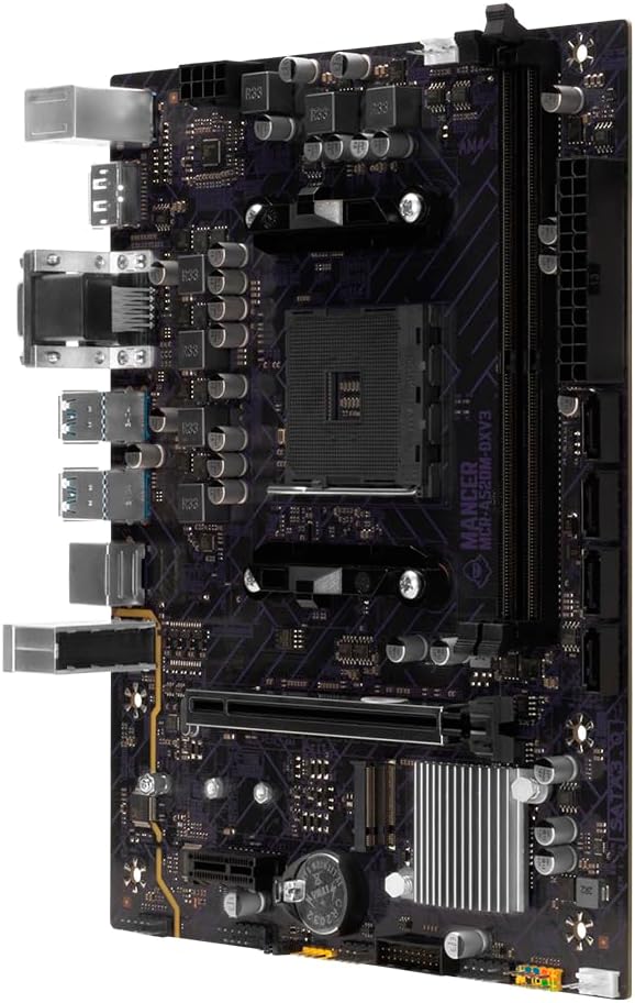
Image: Top-down view of the Mancer A520M DX motherboard, showing the CPU socket, RAM slots, and various connectors.

Image: Angled view of the Mancer A520M DX motherboard, highlighting the various ports and component placement.
2. CPU Installation
- Locate the AM4 socket on the motherboard.
- Lift the load lever on the side of the socket.
- Carefully align the triangular mark on the CPU with the mark on the socket.
- Gently place the CPU into the socket without forcing it.
- Lower the load lever to secure the CPU.
- Install the CPU cooler according to its manufacturer's instructions.
3. Memory (RAM) Installation
- Open the clips at both ends of the DDR4 DIMM slots.
- Align the notch on the memory module with the notch in the DIMM slot.
- Press down firmly on both ends of the memory module until the clips snap into place.
- This motherboard supports 2 x DDR4 DIMM slots with a maximum frequency of 3600MHz and a maximum capacity of 64GB.
4. Storage Device Installation
M.2 SSD Installation:
- Locate the M.2 PCIe 3.0 interface slot.
- Remove the M.2 screw and standoff.
- Insert the M.2 SSD into the slot at an angle.
- Press down the SSD and secure it with the screw.
SATA Drive Installation:
- Connect one end of a SATA data cable to one of the 4 SATA 3.0 ports on the motherboard.
- Connect the other end of the SATA data cable to your SATA hard drive or SSD.
- Connect a SATA power cable from your power supply to the drive.
5. Graphics Card Installation (PCI-E)
- Locate the PCI-E 3.0 16x slot.
- Remove the corresponding expansion slot cover from your PC case.
- Align the graphics card with the PCI-E slot and press down firmly until it is seated.
- Secure the graphics card to the case with a screw.
- Connect any necessary PCI-E power cables from your power supply to the graphics card.
6. Power Supply Connections
- Connect the 24-pin ATX power connector from your power supply to the 24-pin power socket on the motherboard.
- Connect the 8-pin ATX12V power connector from your power supply to the 8-pin power socket near the CPU.
7. Front Panel and Other Connections
Connect the front panel connectors (power button, reset button, HDD LED, power LED), USB ports, and audio jacks from your PC case to the corresponding headers on the motherboard. Refer to the motherboard diagram for exact locations.
8. Rear I/O Panel Overview
The rear I/O panel provides various connectivity options.

Image: Close-up view of the Mancer A520M DX motherboard's rear I/O panel, showing PS/2, USB, DisplayPort, VGA, HDMI, Gigabit Ethernet, and audio ports.
- PS/2 Ports: For legacy keyboard and mouse.
- USB 2.0 Ports: For peripherals.
- DisplayPort (DP): For video output.
- VGA Port: For video output.
- HDMI Port: For video and audio output.
- USB 3.2 10GB/s Ports: High-speed USB connections.
- Gigabit Ethernet Port: For network connectivity.
- Audio Jacks: For audio input/output.
Operating Instructions
BIOS Setup
The BIOS (Basic Input/Output System) is firmware that initializes hardware during the booting process. To enter the BIOS setup utility, press the DEL or F2 key repeatedly during system startup. Here you can configure system settings, boot order, and monitor hardware status.
Driver Installation
After installing your operating system, install the necessary drivers for the motherboard chipset, audio, LAN, and any other integrated components. These drivers are typically provided on a support CD/DVD or can be downloaded from the Mancer official website.
Maintenance
Cleaning
Regularly clean your PC to prevent dust buildup, which can lead to overheating and component failure. Use compressed air to remove dust from fans, heatsinks, and other components. Ensure the system is powered off and unplugged before cleaning.
BIOS Updates
Periodically check the Mancer website for BIOS updates. BIOS updates can improve system stability, add support for new CPUs or memory, and fix bugs. Follow the instructions provided by Mancer carefully when updating the BIOS to avoid system damage.
Troubleshooting
- No Power: Ensure all power cables (24-pin ATX, 8-pin ATX12V) are securely connected to the motherboard and power supply. Check the power supply unit (PSU) switch and wall outlet.
- No Display: Verify that the monitor is connected to the correct video output (VGA, HDMI, or DP) on the motherboard or dedicated graphics card. Reseat the graphics card and RAM modules.
- System Instability/Crashes: Check RAM seating and compatibility. Ensure CPU cooler is properly installed and making good contact. Update drivers and BIOS.
- Boot Issues: Check boot order in BIOS. Ensure storage drives are properly connected and detected.
- Peripheral Not Detected: Try different USB ports. Ensure drivers are installed for the peripheral.
For more complex issues, consult the Mancer support website or contact technical support.
Specifications
| Feature | Description |
|---|---|
| Model | MCR-A520M-DXV3 |
| CPU Support | AMD AM4 Socket (Ryzen 3000, 4000, 5000 series; 4000G, 5000G series) |
| Chipset | AMD A520 |
| Memory | 2 x DDR4 DIMM slots, up to 3600MHz, Max 64GB |
| Storage | 1 x M.2 PCIe 3.0 interface, 4 x SATA 3.0 ports |
| Display Interface | 1 x VGA, 1 x HDMI, 1 x DP |
| Rear I/O | PS/2, USB 2.0, DP, VGA, HDMI, USB 3.2 10GB/s, Gigabit Ethernet, Audio Jacks |
| Internal I/O | 2F USB 2.0 (exp. 4 USB 2.0), 1F USB 3.0 (exp. 2 USB 3.0), F_AUDIO, COM 232, JCMOS, CPU Fan, 2x SYSFAN, Speaker |
| Expansion Slots | 1 x PCI-E 3.0 16x, 1 x PCI-E 1x |
| Power Connectors | 1 x 24-pin ATX, 1 x 8-pin ATX12V |
| Dimensions | 180 x 225 mm |
Warranty Information
Mancer products are covered by a limited warranty. Please refer to the warranty card included with your product or visit the official Mancer website for detailed warranty terms and conditions. Keep your proof of purchase for warranty claims.
Support
For technical assistance, driver downloads, or further information, please visit the official Mancer support website. You may also contact Mancer customer service through the channels provided on their website.
Mancer Official Website: www.mancer.com.br (Example link, please verify actual support URL)