GY-25A
Generic GY-25A High-Precision Dual-Axis Tilt Sensor Module User Manual
Model: GY-25A
1. Introduction
The Generic GY-25A is a high-precision dual-axis tilt detection sensor module designed to measure inclination along two axes. This module provides analog and serial port output, making it suitable for various applications requiring accurate tilt sensing. It can serve as an alternative to the SCA60C module.
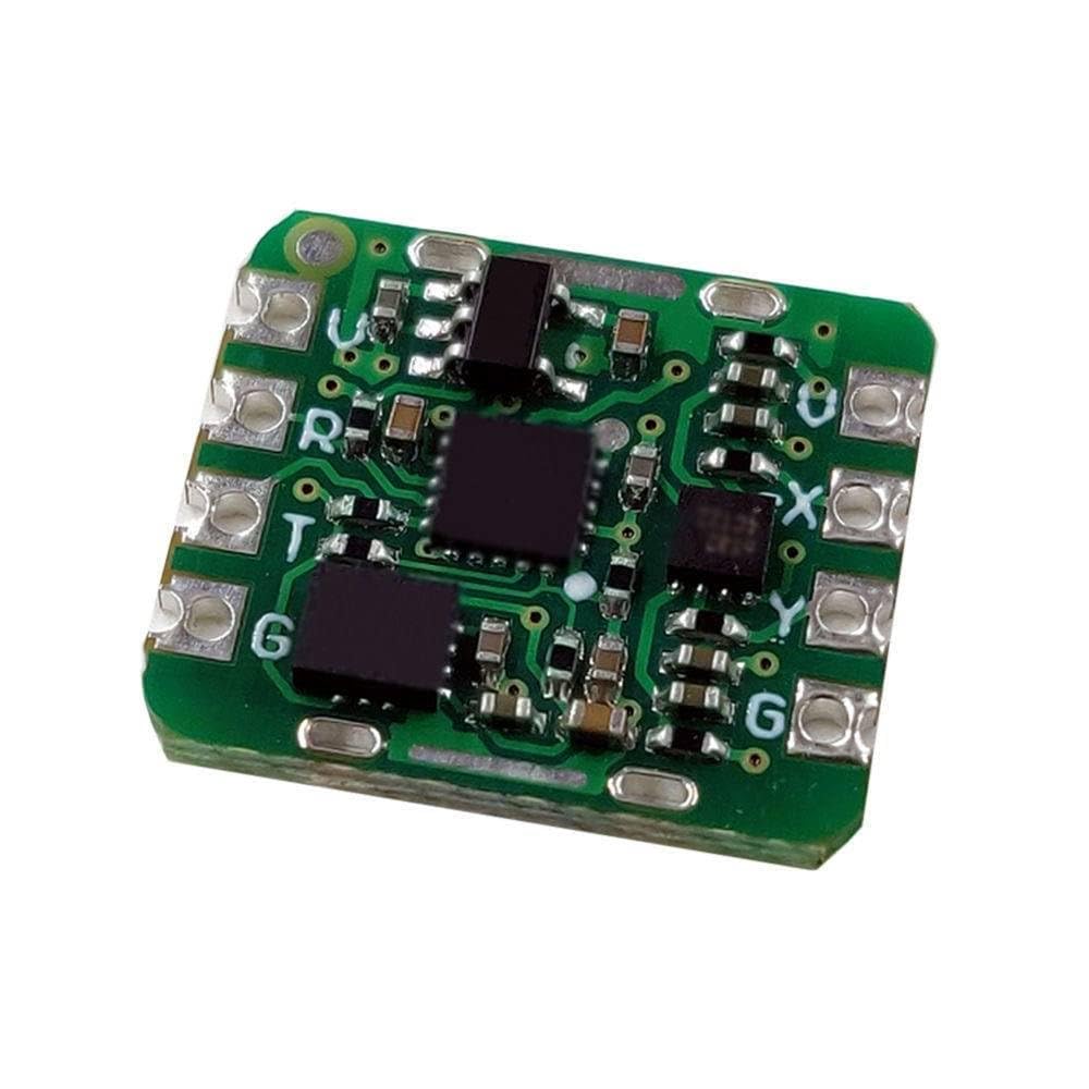
Figure 1: GY-25A Dual-Axis Tilt Sensor Module. This image displays the GY-25A sensor module, a compact green circuit board featuring multiple integrated circuits and clearly marked connection points for power, ground, and data.
2. Features
- High-precision dual-axis tilt detection.
- Analog and serial port output options.
- Compact module design.
- Suitable for various industrial and scientific applications.
- Can be used as a replacement for SCA60C modules.
3. Specifications
| Parameter | Value |
|---|---|
| Model | GY-25A |
| Detection Axes | Dual-axis (X, Y) |
| Output Type | Analog, Serial Port |
| Manufacturer | Generic |
| ASIN | B0DHS2VZLK |
| First Available | September 23, 2024 |
4. Setup
This section provides general guidelines for setting up the GY-25A module. Specific wiring and programming details may vary based on your microcontroller or system.
4.1. Pinout Description
Refer to the module's silkscreen for pin labels. Common pins typically include:
- VCC: Power supply input (e.g., 3.3V or 5V, check module documentation for exact voltage).
- GND: Ground connection.
- TX/RX: Serial communication pins (for serial port output).
- AX/AY: Analog output pins for X and Y axis tilt (if applicable).
4.2. Wiring
- Connect the VCC pin of the GY-25A module to the appropriate power supply output of your microcontroller or power source.
- Connect the GND pin of the GY-25A module to the ground of your system.
- For serial communication, connect the TX pin of the GY-25A to the RX pin of your microcontroller, and the RX pin of the GY-25A to the TX pin of your microcontroller.
- For analog output, connect the AX and AY pins to analog input pins on your microcontroller.
Note: Always ensure correct voltage levels and pin connections to prevent damage to the module or host device. Consult the specific datasheet for detailed pin descriptions and electrical characteristics.
5. Operating Instructions
5.1. Serial Communication
The GY-25A module typically outputs tilt data via a serial interface (UART). To read data:
- Initialize your microcontroller's UART peripheral with the correct baud rate (e.g., 9600, 115200 bps, refer to module's specific documentation).
- Read incoming bytes from the serial port. The data format will typically be a structured packet containing X and Y axis tilt values.
- Parse the received data to extract the tilt angles.
5.2. Analog Output
If using analog output, the module provides voltage levels proportional to the tilt angle.
- Connect the analog output pins (AX, AY) to the Analog-to-Digital Converter (ADC) inputs of your microcontroller.
- Read the analog voltage values from these pins.
- Convert the raw ADC readings to voltage, and then use the module's sensitivity (mV/degree) to calculate the tilt angle. This sensitivity value should be available in the module's datasheet.
Tip: For initial testing, connect the module to a serial terminal program on a computer to verify data output before integrating with a microcontroller.
6. Maintenance
The GY-25A module is a robust electronic component and requires minimal maintenance. Follow these guidelines to ensure its longevity:
- Keep Dry: Avoid exposure to moisture or liquids, which can damage the electronic components.
- Cleanliness: Keep the module free from dust and debris. Use a soft, dry brush or compressed air for cleaning if necessary.
- Temperature: Operate and store the module within its specified temperature range to prevent performance degradation or damage.
- Physical Protection: Handle the module carefully to avoid physical shock or bending of the PCB. Consider enclosing it in a protective casing for long-term deployment.
7. Troubleshooting
- No Data Output (Serial):
- Verify power and ground connections are secure.
- Check TX/RX wiring for correct cross-connection (TX to RX, RX to TX).
- Ensure the baud rate configured in your software matches the module's baud rate.
- Confirm the module is receiving adequate power.
- Incorrect Tilt Readings:
- Ensure the module is mounted securely and not vibrating.
- Check for electromagnetic interference from nearby components.
- If using analog output, verify the ADC reference voltage and conversion calculations.
- Calibrate the sensor if the documentation provides a calibration procedure.
- Module Not Powering On:
- Double-check power supply voltage and polarity.
- Inspect for any visible damage to the module or connections.
8. Warranty and Support
This product is manufactured by Generic. For specific warranty information or technical support, please refer to the retailer or distributor from whom the product was purchased. General support for electronic components often includes resources such as online forums, community support, and manufacturer datasheets available through their respective websites.
For further assistance, you may also consult relevant online communities or educational platforms dedicated to electronics and sensor integration.
Ask a question about this manual
Ask about setup, troubleshooting, compatibility, parts, safety, or missing instructions. Manuals+ will review the question and use this page’s manual context to help answer it.