1. Product Overview
The OJOPOV TXAPS3-100 is an intelligent three-phase selector voltmeter with integrated over and under voltage protection relays and an automatic changeover switch. It is designed to ensure uninterrupted power supply to essential single-phase loads by automatically selecting the optimal power source based on voltage presence and quality across different phases.
This device provides comprehensive protection against voltage fluctuations and overcurrent conditions, safeguarding connected electrical equipment. It features real-time voltage display and allows for voltage calibration and priority power source setting.

Figure 1: OJOPOV Three Phase Selector Voltmeter (TXAPS3-100)
This image displays the front view of the OJOPOV Three Phase Selector Voltmeter, showing its digital voltage displays for L1, L2, and L3, control buttons, and fault indicators. The device is designed for DIN rail mounting.
2. Key Features
- Overvoltage Protection: Automatically disconnects power when voltage exceeds a safe threshold.
- Under-voltage Protection: Automatically disconnects power when voltage drops below a safe threshold.
- Voltage Display: Real-time digital display of voltage for each phase (L1, L2, L3).
- Voltage Calibration: Allows for fine-tuning of voltage readings (±9.5% adjustable).
- Automatic Changeover: Seamlessly transfers load to an alternative power supply if the current supply experiences over/under voltage or failure.
- Overcurrent Protection: Instantly cuts off power in case of an overcurrent fault to protect connected equipment.
- Priority Phase Setting: User-configurable priority for power resources. The device will revert to the priority source once it recovers to normal voltage.
3. Safety Information
WARNING: Electrical shock hazard. Installation and maintenance should only be performed by qualified electricians.
- Always disconnect power before installing, servicing, or removing the device.
- Ensure all wiring conforms to local and national electrical codes.
- Verify correct voltage and current ratings before connection. This device is rated for 100A.
- Do not operate the device if it appears damaged.
- Keep the device away from moisture and extreme temperatures.
4. Panel Introduction
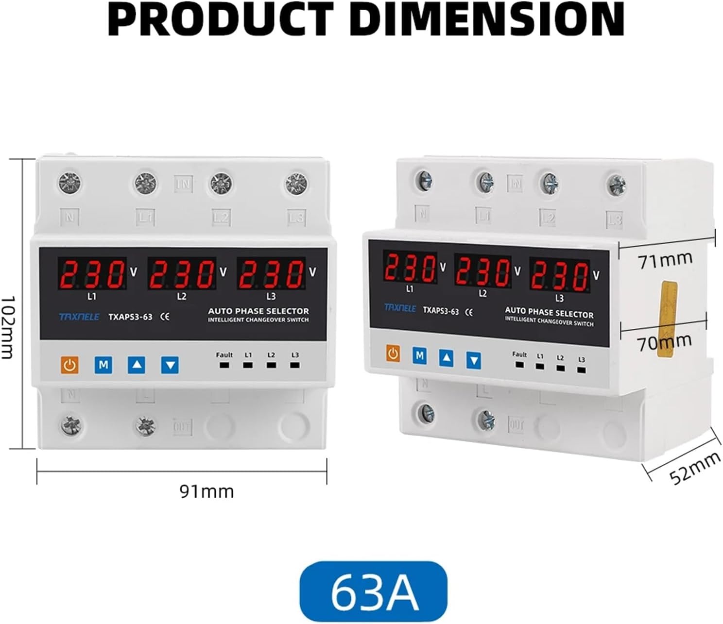
Figure 2: Front Panel Layout and Indicators
This image illustrates the various controls and indicators on the front panel of the device. It shows the digital displays for L1, L2, L3 voltages, and the control buttons below them. On the right, there are LED indicators for Fault, L1, L2, and L3.
| Symbol/Indicator | Description |
|---|---|
| ⏻ (Power Button Icon) | Manual Switch: Used for manual operation or power control. |
| M | Menu Key: Used to access and navigate through settings menus. |
| ▲ (Up Arrow) | Adjustment Key +: Used to increase values or move up in menus. |
| ▼ (Down Arrow) | Adjustment Key -: Used to decrease values or move down in menus. |
| Fault | Fault Indicator: Illuminates to indicate a fault condition (e.g., over/under voltage, overcurrent). |
| L1 | First Phase Power-on Indicator: Illuminates when L1 phase is active. |
| L2 | Second Phase Power-on Indicator: Illuminates when L2 phase is active. |
| L3 | Third Phase Power-on Indicator: Illuminates when L3 phase is active. |
5. Setup and Installation
The OJOPOV TXAPS3-100 is designed for DIN rail mounting within an electrical panel. Proper installation is crucial for safe and reliable operation.
5.1 Wiring Diagram (General Guidance)
This device requires a 3-phase + Neutral (3P+N) connection. Ensure that the incoming power lines (L1, L2, L3, N) are correctly connected to the 'IN' terminals and the outgoing load lines to the 'OUT' terminals. Refer to the markings on the device for precise terminal identification.
- Connect the incoming L1, L2, L3, and Neutral lines to the corresponding input terminals (IN).
- Connect the outgoing L1, L2, L3, and Neutral lines to the corresponding output terminals (OUT) that lead to your load.
- Ensure all connections are tight and secure to prevent loose contacts and overheating.
- It is recommended to install an appropriate circuit breaker upstream of the device for additional protection and isolation.

Figure 3: Example of Output Connection
This image shows the bottom terminals of the device with red wires connected, indicating the power output. It highlights the "best Power Resource Output" feature, demonstrating how the device provides power to the load.
6. Operating Instructions
6.1 Power On and Initial Display
Once correctly wired and power is supplied, the device will power on and display the real-time voltage for each connected phase (L1, L2, L3) on its digital screens.

Figure 4: Real-time Voltage Display
This image demonstrates the real-time voltage display feature, showing the digital readouts for L1, L2, and L3. It also indicates that over/under voltage values are adjustable.
6.2 Automatic Changeover Function
The device continuously monitors the voltage quality of all connected phases. If the current power supply experiences over-voltage, under-voltage, or a complete failure, the TXAPS3-100 will automatically transfer the load to another stable power supply to ensure uninterrupted operation.

Figure 5: Uninterrupted Power Supply
This image visually explains the uninterrupted power feature, showing how the device automatically transfers to another power supply when the current one is over/under voltage or stops.
6.3 Setting Priority Phase
You can configure a priority power source. When the priority phase recovers to normal voltage conditions after a transfer, the device will automatically switch the load back to the designated priority power resource.
- Press the M (Menu) Key to enter the settings menu.
- Navigate using the Adjustment Keys (▲ / ▼) to find the "Priority Setting" option.
- Press M again to select and adjust the priority order (e.g., ABC, ACB, BAC, etc.).
- Confirm your selection by pressing M or waiting for the setting to auto-save.

Figure 6: Priority Phase Setting Options
This image illustrates the concept of priority phase setting, showing various possible phase orders (ABC, ACB, BAC, BCA, CAB, CBA) that can be configured for the automatic changeover switch.
6.4 Voltage Calibration
If the displayed voltage readings are not accurate, you can calibrate them:
- Press the M (Menu) Key to enter the settings menu.
- Navigate using the Adjustment Keys (▲ / ▼) to find the "Voltage Calibration" option.
- Press M again to select. Use the Adjustment Keys (▲ / ▼) to adjust the voltage value within the ±9.5% range.
- Confirm your adjustment by pressing M or waiting for the setting to auto-save.
7. Maintenance
The OJOPOV TXAPS3-100 is designed for minimal maintenance. However, regular checks can ensure its longevity and reliable operation:
- Visual Inspection: Periodically inspect the device for any signs of physical damage, discoloration, or loose connections.
- Cleaning: Keep the device clean and free from dust and debris. Use a dry, soft cloth for cleaning. Do not use liquid cleaners.
- Connection Check: Ensure all wiring terminals remain tight. Loose connections can lead to overheating and malfunction.
CAUTION: Always disconnect power before performing any maintenance or inspection.
8. Troubleshooting
If you encounter issues with your OJOPOV TXAPS3-100, refer to the following common problems and solutions:
| Problem | Possible Cause | Solution |
|---|---|---|
| Device does not power on. | No power supply; incorrect wiring; internal fault. | Check incoming power supply. Verify wiring connections. If problem persists, contact support. |
| "Fault" indicator is lit. | Over-voltage, under-voltage, or overcurrent detected. | Check input voltage levels. Check load for overcurrent. The device has likely tripped for protection. Address the underlying electrical issue. |
| No automatic transfer. | No alternative stable power source; device settings. | Ensure all phases have a valid power supply. Check priority settings and voltage thresholds. |
| Inaccurate voltage display. | Needs calibration. | Perform voltage calibration as described in Section 6.4. |
9. Specifications
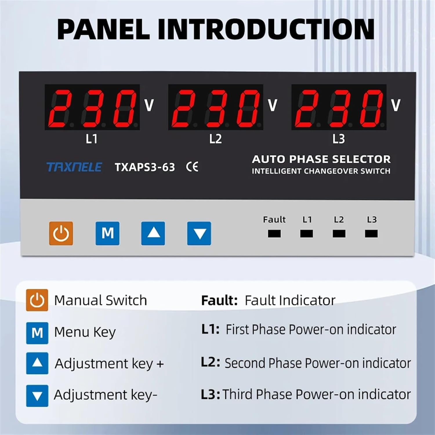
Figure 7: Product Dimensions (Note: Image shows 63A model, dimensions for 100A model are similar)
This image provides a visual representation of the product's dimensions, including height, width, and depth. While specifically showing the 63A model, the overall form factor and approximate dimensions are indicative for the 100A model as well.
| Parameter | Value |
|---|---|
| Model | TXAPS3-100 |
| Rated Current | 100A |
| Voltage Protection | Over-voltage, Under-voltage |
| Voltage Calibration | ±9.5% adjustable |
| Phase Configuration | 3P+N (Three Phase + Neutral) |
| Type | Miniature Circuit Breaker (Intelligent Transfer Switch) |
| Manufacturer | OJOPOV |
| Item Weight | 1.76 ounces (approx. 50g) |
| Package Dimensions | 1.18 x 0.79 x 0.39 inches (approx. 30 x 20 x 10 mm) |
10. Warranty and Support
For warranty information and technical support, please refer to the documentation provided with your purchase or contact the manufacturer directly. Keep your purchase receipt as proof of purchase.
Manufacturer: OJOPOV
For further assistance, please visit the official OJOPOV website or contact their customer service department.