1. Introduction
This manual provides detailed instructions for the installation, operation, and maintenance of your MGBIDMI 3KVA/2400W-24V Hybrid Off Grid Solar Inverter. Please read this manual thoroughly before installation and use to ensure proper function and safety.
Key Features:
- Pure sine wave inverter output.
- Integrated 50A PWM solar charge controller.
- Selectable input voltage range for various applications.
- Configurable AC/solar input priority via LCD settings.
- Automatic restart upon AC recovery.
- Smart fan for efficient heat dissipation.
- Multiple protection functions: overload, short circuit, overcharge.
- Intelligent battery charger design.
- Supports 4 charging modes: Only Solar, Mains Priority, Solar Priority, Mains & Solar hybrid.
2. Safety Information
Please observe the following safety precautions to prevent injury and damage to the inverter:
- Installation must be performed by qualified personnel.
- Ensure all connections are secure and correct before operation.
- Do not disassemble the inverter. There are no user-serviceable parts inside.
- Keep the inverter away from water, flammable materials, and corrosive substances.
- Ensure adequate ventilation around the inverter to prevent overheating.
- Always disconnect power before performing any maintenance or wiring.
3. Product Overview
The MGBIDMI Hybrid Off Grid Solar Inverter is designed to provide reliable power for various applications. Below are key aspects and components of the unit.

Figure 3.1: MGBIDMI Hybrid Off Grid Solar Inverter with example application scenarios including solar panels, wind turbines, and a home power system diagram.

Figure 3.2: System diagram illustrating the connection of solar panels, generator/mains, the inverter, battery, and various household loads (computer, laptop, fan, light bulb).
Front Panel and Connections:

Figure 3.3: Front panel and rear connection points of the inverter. Key components include the LCD Display (1), LED Indicators (2), Function Keys (3), Power Switch (4), AC Input (5), AC Output (6), RS232 Port (7), Circuit Breaker (8), Safety (Earth) Ground (9), Battery Negative (10), Battery Positive (11), and PV Input (12).
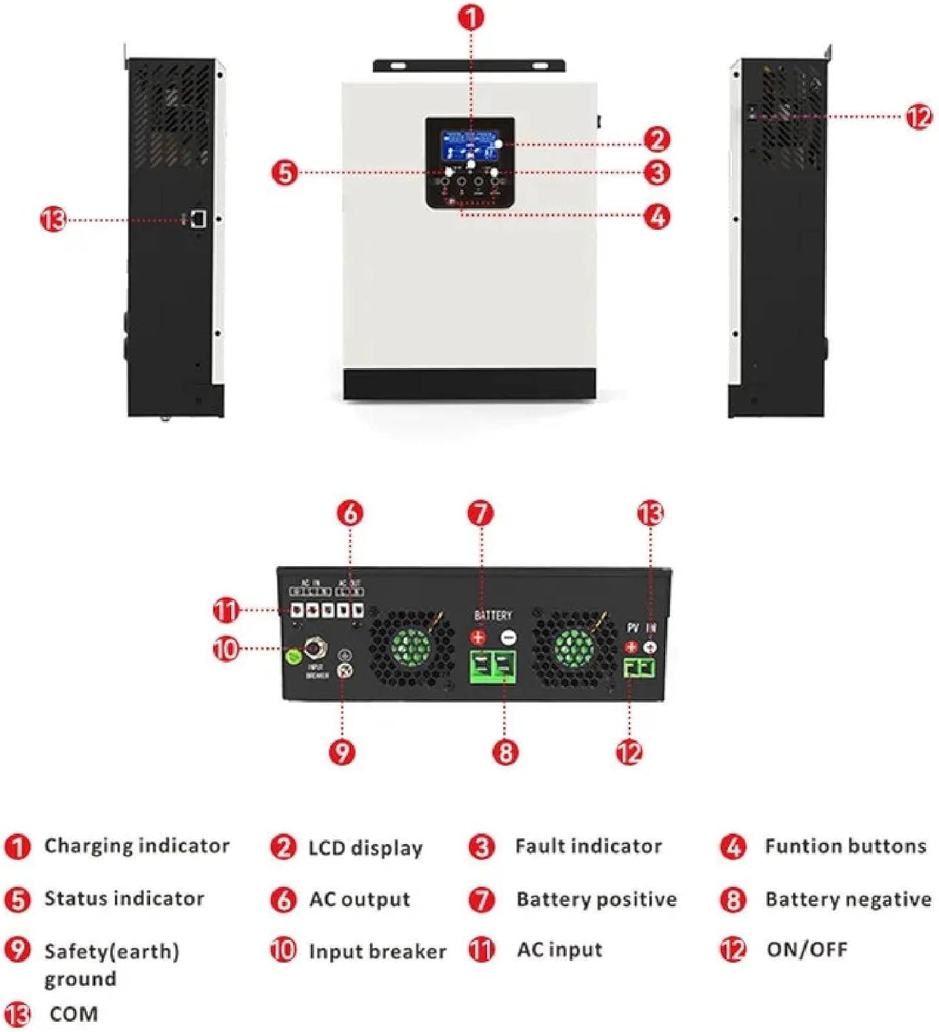
Figure 3.4: Another perspective of the inverter's connections and indicators. Labels include Charging indicator (1), LCD display (2), Fault indicator (3), Function buttons (4), Status indicator (5), AC output (6), Battery positive (7), Battery negative (8), Safety (earth) ground (9), Input breaker (10), AC input (11), ON/OFF switch (12), and COM port (13).
4. Setup and Installation
Proper installation is crucial for the safe and efficient operation of your inverter. Follow these general guidelines:
- Mounting: Choose a dry, well-ventilated area, away from direct sunlight and heat sources. Ensure the mounting surface can support the inverter's weight.
- Battery Connection: Connect the battery bank to the inverter's battery terminals (positive to positive, negative to negative). Ensure correct polarity. Refer to Figure 3.3 and 3.4 for terminal locations.
- PV Input Connection: Connect the solar panel array to the PV input terminals. Observe correct polarity and ensure the PV array voltage is within the specified operating range (30-80Vdc).
- AC Input Connection: Connect the AC mains power supply to the AC input terminal. This allows for battery charging from the grid and bypass operation.
- AC Output Connection: Connect your AC loads to the AC output terminals. Ensure the total load does not exceed the inverter's rated power (2400W).
- Grounding: Connect the safety (earth) ground terminal to a reliable earth ground.
- Power On: After all connections are secure and verified, switch on the power breaker (if present) and then the inverter's ON/OFF switch.
Warning: Incorrect wiring can cause severe damage to the inverter and connected equipment, and poses a risk of electric shock. Consult a qualified electrician if unsure.
5. Operating Instructions
LCD Display and Indicators:
The inverter features an LCD display and LED indicators to provide real-time status and allow for configuration. Refer to Figure 3.3 for visual identification.
| LED Indicator | Messages |
|---|---|
| AC / INV (Green) | Solid On: Output is powered by utility in Line mode. Flashing: Output is powered by battery or PV in battery mode. |
| CHG (Green) | Solid On: Battery is fully charged. Flashing: Battery is charging. |
| FAULT (Red) | Solid On: Inverter is in fault. Flashing: Warning condition occurs in the inverter. |
Function Keys:
The function keys (ESC, UP, DOWN, ENTER) allow navigation and selection within the LCD menu. Refer to Figure 3.3 for key locations.
| Function Key | Description |
|---|---|
| ESC | To exit setting mode. |
| UP | To go to previous selection. |
| DOWN | To go to next selection. |
| ENTER | To confirm the selection in setting mode or enter setting mode. |
Configurable Settings:
The inverter allows users to configure various settings via the LCD display and function keys, including:
- AC/Solar Input Priority: Set whether the inverter prioritizes AC mains or solar power for charging and load supply.
- Charging Current: Adjust the battery charging current based on battery specifications.
- Input Voltage Range: Select between "personal computers" (170-280 VAC) or "home appliances" (90-280 VAC) for AC input.
- Charging Modes: Choose from Only Solar, Mains Priority, Solar Priority, or Mains & Solar hybrid charging.
- Sectional Charging/Discharge: Set specific time periods (00:00 to 23:59) for battery discharge or mains charging, useful for optimizing based on electricity tariffs.
6. Maintenance
Regular maintenance ensures the longevity and optimal performance of your inverter:
- Cleaning: Periodically clean the exterior of the inverter with a dry cloth. Ensure ventilation openings are free from dust and debris.
- Connections: Annually inspect all electrical connections (battery, PV, AC input/output) for tightness and corrosion. Tighten any loose connections.
- Battery Inspection: Check battery terminals for corrosion and ensure battery fluid levels (if applicable) are correct.
- Environment: Ensure the operating environment remains within specified temperature and humidity ranges.
- Firmware: Check the manufacturer's website for any available firmware updates.
Caution: Disconnect all power sources before performing any cleaning or inspection.
7. Troubleshooting
If you encounter issues with your inverter, refer to the LED indicators and the following common troubleshooting steps:
- No Power Output:
- Check if the inverter is switched on.
- Verify battery connections and voltage.
- Check AC input and output circuit breakers.
- Ensure the battery is not deeply discharged.
- Fault LED On:
- Refer to the LCD display for specific error codes or messages.
- Common faults include overload, short circuit, over-temperature, or battery issues.
- Disconnect loads, allow the unit to cool, and restart.
- Battery Not Charging:
- Check PV input connections and voltage from solar panels.
- Verify AC input connection if charging from mains.
- Ensure charging current settings are appropriate.
- Check battery health.
- Inverter Overload:
- Reduce the connected load. The inverter will typically attempt to restart automatically after an overload condition.
If the problem persists after following these steps, contact customer support.
8. Specifications
Detailed technical specifications for the MGBIDMI 3KVA/2400W-24V Hybrid Off Grid Solar Inverter:
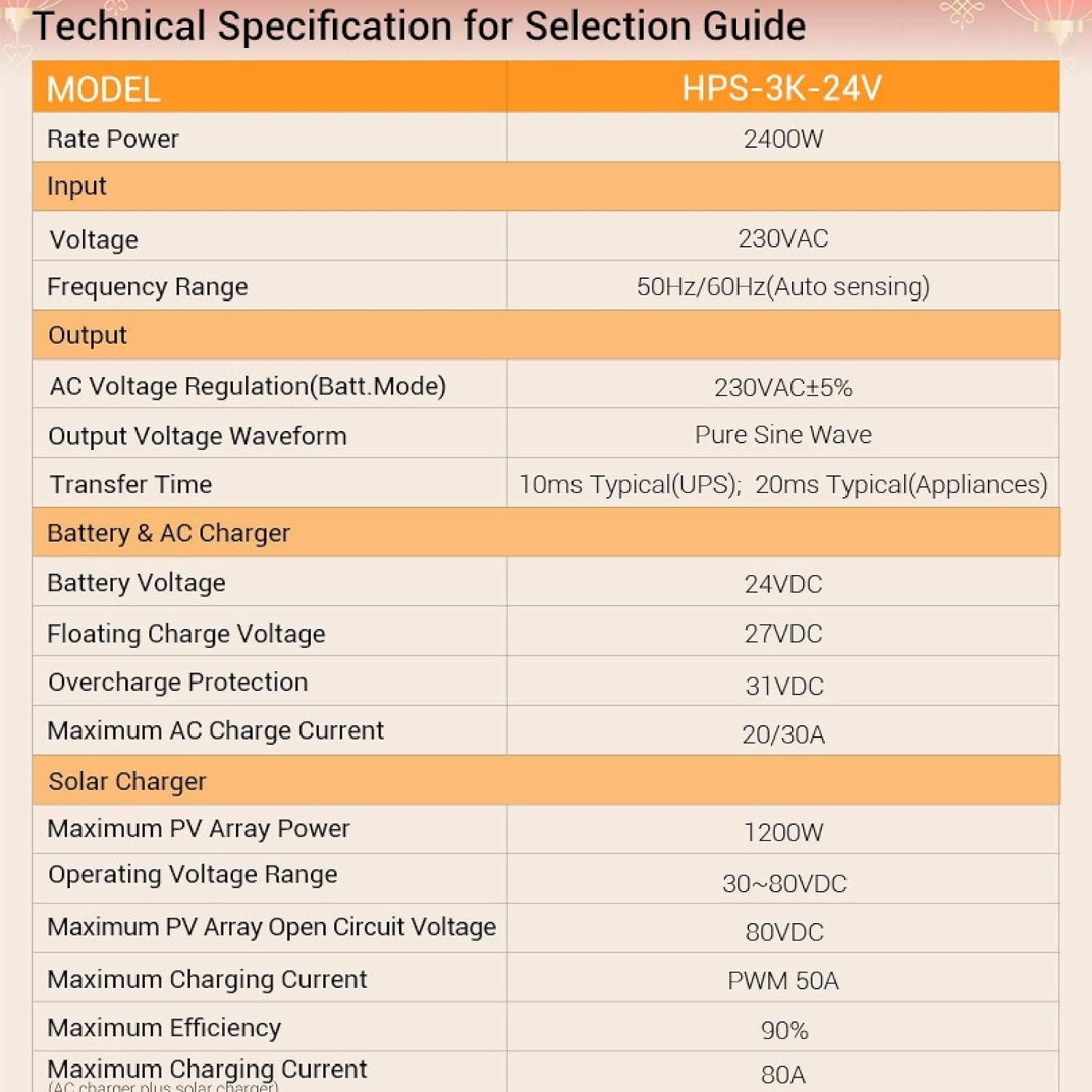
Figure 8.1: Technical Specifications for the HPS-3K-24V Inverter.
| Model: HPS-3K-24V | |
|---|---|
| Rated Power | 2400W |
| Input | |
| Voltage | 230VAC |
| Selectable Voltage Range (Personal Computers) | 170-280 VAC |
| Selectable Voltage Range (Home Appliances) | 90-280 VAC |
| Frequency Range | 50 Hz/60 Hz (adaptive) |
| Output | |
| AC Voltage Regulation Rate (Battery Mode) | 230VAC±5% |
| Surge Power | 6000VA |
| Efficiency (Peak) | 93% |
| Transfer Time (Personal Computers) | 10ms |
| Transfer Time (Home Appliances) | 20ms |
| Waveform | Pure Sine Wave |
| Battery & AC Charging | |
| Battery Voltage | 24VDC |
| Float Charging Voltage | 27VDC |
| Overcharge Protection Voltage | 31VDC |
| Maximum AC Charging Current | 20/30A |
| PWM Solar Charger | |
| Maximum Photovoltaic Array Power | 1200W |
| Charging Current | 50A |
| Working Voltage Range | 30~80Vdc |
| Maximum Open Circuit Voltage of PV Array | 80Vdc |
| Maximum Charging Current (AC+Solar) | 80A |
| Charging Mode | PWM |
| Maximum Efficiency | 90% |
Dimensions:

Figure 8.2: Inverter dimensions: Approximately 272mm (width) x 305mm (height) x 100mm (depth).
9. Warranty and Support
For warranty information and technical support, please refer to the warranty card included with your product or contact MGBIDMI customer service through their official channels. Please have your model number (3KVA/2400W-24V) and purchase details ready when contacting support.
For further assistance, visit the MGBIDMI website or contact your local distributor.


