1. Introduction
This manual provides essential information for the safe and effective operation of your CHUNYE DC1040 Series PID Temperature Controller. This device is designed for precise temperature regulation in various industrial and scientific applications. Please read this manual thoroughly before installation and operation.
2. Safety Information
- Ensure all wiring is performed by qualified personnel and complies with local electrical codes.
- Disconnect power before performing any installation, wiring, or maintenance.
- Do not operate the controller in environments exceeding its specified temperature and humidity limits.
- Protect the device from moisture, dust, and corrosive gases.
- Verify correct sensor type and wiring before powering on to prevent damage or inaccurate readings.
3. Product Overview
The CHUNYE DC1040 Series PID Temperature Controller features a clear digital display and intuitive controls for precise temperature management.
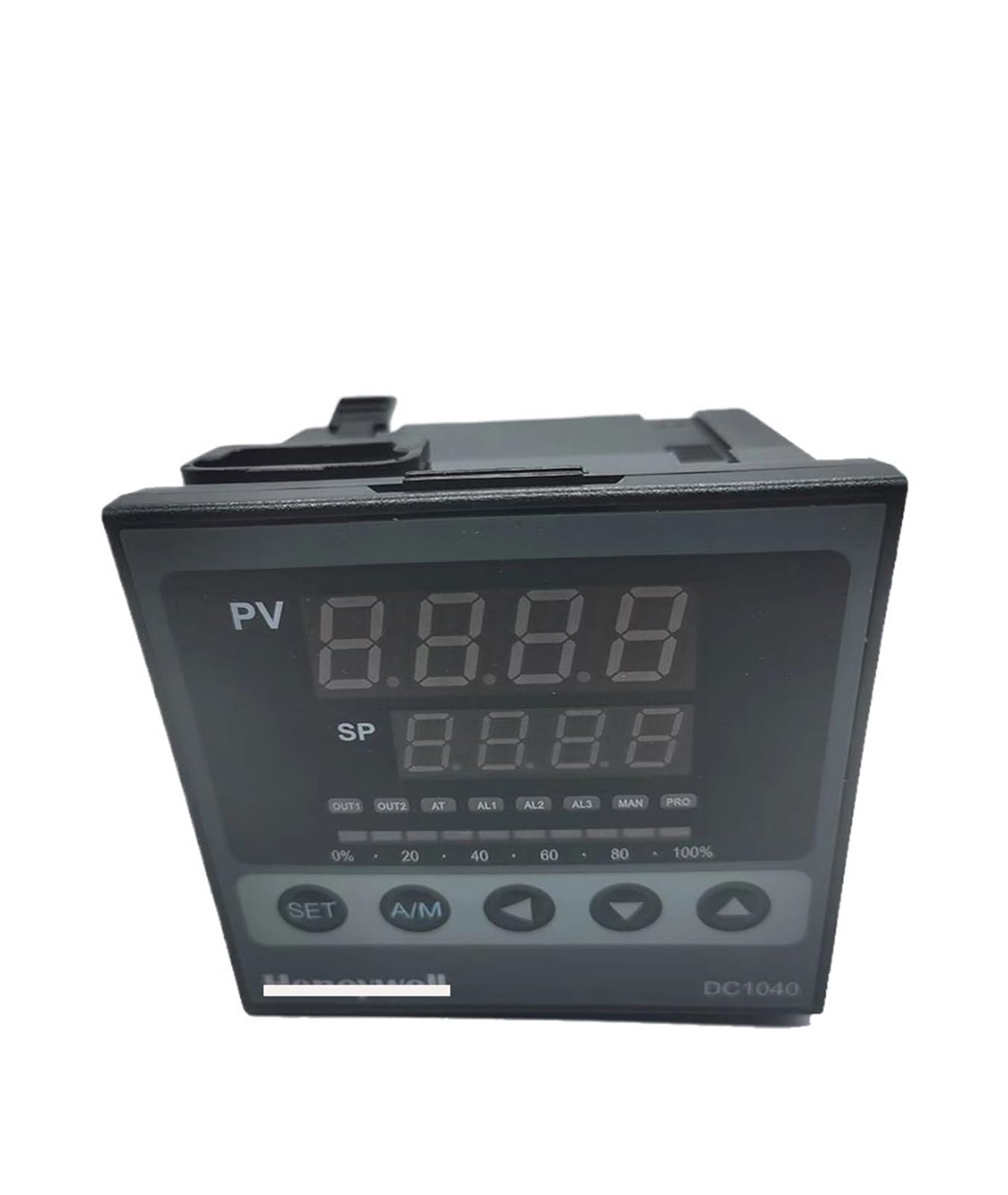
Figure 1: Front panel of the CHUNYE DC1040 PID Temperature Controller. It features two large digital displays, labeled PV (Process Value) and SP (Set Point), showing current and target temperatures respectively. Below the displays are indicator lights for OUT1, OUT2, AT (Auto-Tune), AL1, AL2, AL3 (Alarms), MAN (Manual mode), and PRO (Program mode). A percentage bar from 0% to 100% indicates output power. Control buttons include SET, A/M (Auto/Manual), and arrow keys (Left, Down, Up) for navigation and value adjustment.
3.1. Display and Indicators
- PV (Process Value): Displays the current measured temperature.
- SP (Set Point): Displays the target temperature.
- OUT1/OUT2: Output indicators, typically for heating/cooling elements.
- AT (Auto-Tune): Indicates auto-tuning process is active.
- AL1/AL2/AL3: Alarm indicators.
- MAN (Manual): Indicates manual control mode.
- PRO (Program): Indicates program/profile control mode.
- Output Percentage Bar: Shows the current output power level (0-100%).
3.2. Control Buttons
- SET: Enters parameter setting mode or confirms a setting.
- A/M (Auto/Manual): Toggles between automatic and manual control modes.
- Left Arrow (<): Shifts cursor position during parameter setting.
- Down Arrow (▼): Decreases parameter value.
- Up Arrow (▲): Increases parameter value.
4. Setup and Installation
4.1. Mounting
The DC1040 controller is designed for panel mounting. Ensure adequate space for ventilation and wiring connections at the rear. Secure the controller using the provided mounting brackets.
4.2. Wiring
Refer to the wiring diagram provided with your specific model for detailed connection instructions. General wiring considerations include:
- Power Supply: Connect to the specified voltage (e.g., 100-240V AC).
- Sensor Input: Connect your temperature sensor (e.g., thermocouple, RTD) to the designated input terminals. Ensure correct polarity for thermocouples.
- Control Output: Connect your heating/cooling element or SSR to the output terminals (OUT1, OUT2).
- Alarm Outputs: If applicable, connect external alarm devices to the alarm output terminals.
Caution: Incorrect wiring can damage the controller and connected equipment. Always verify connections before applying power.
5. Operating Instructions
5.1. Initial Power-On
After successful wiring, apply power. The controller will perform a self-test, and the PV and SP displays will light up.
5.2. Setting the Set Point (SP)
- Press the SET button once. The SP value will begin to flash.
- Use the ▲ (Up) or ▼ (Down) arrow buttons to adjust the SP to your desired temperature.
- Use the < (Left) arrow button to shift the cursor for faster adjustment of individual digits.
- Press SET again to confirm the new SP and exit the setting mode.
5.3. Auto-Tuning (AT)
Auto-tuning helps the controller optimize its PID parameters for stable and accurate temperature control. It is recommended after initial setup or if control performance is unsatisfactory.
- Ensure the SP is set to your desired operating temperature.
- Press and hold the SET button for approximately 3-5 seconds until the AT indicator light begins to flash.
- The controller will cycle the output to determine the system's characteristics. The PV may fluctuate during this process.
- Once auto-tuning is complete, the AT indicator will turn off, and the controller will resume normal PID control with optimized parameters.
5.4. Manual/Automatic Mode Switching
Press the A/M button to toggle between Automatic (PID control) and Manual control modes. In Manual mode, you can directly adjust the output power percentage using the arrow keys.
6. Maintenance
- Cleaning: Regularly wipe the front panel with a soft, dry cloth. Do not use abrasive cleaners or solvents.
- Inspection: Periodically check wiring connections for looseness or signs of damage.
- Environment: Ensure the operating environment remains within specified temperature and humidity ranges to prolong the controller's lifespan.
Warning: Always disconnect power before cleaning or inspecting the controller.
7. Troubleshooting
| Problem | Possible Cause | Solution |
|---|---|---|
| No display/Power off | No power supply; Incorrect wiring; Blown fuse. | Check power connection; Verify wiring; Replace fuse if necessary. |
| PV display shows 'HHHH' or 'LLLL' | Sensor open circuit (HHHH); Sensor short circuit (LLLL); Incorrect sensor type setting. | Check sensor wiring; Replace faulty sensor; Verify sensor type parameter setting. |
| Temperature control is unstable/oscillating | PID parameters not optimized; External disturbances. | Perform auto-tuning; Check for drafts or sudden temperature changes in the environment. |
| Output not activating | Incorrect output wiring; Output device faulty; Controller in manual mode with 0% output. | Verify output wiring; Test output device; Switch to auto mode or increase manual output. |
8. Specifications
| Feature | Specification |
|---|---|
| Model Series | DC1040 Series |
| Control Method | PID Control (Auto-tune function) |
| Input Type | Various Thermocouple (K, J, E, T, R, S, B, N, W5Re/W26Re, PLII), RTD (Pt100, JPt100) |
| Output Options | Relay, SSR, Current (depending on model) |
| Display | Dual 4-digit LED (PV & SP) |
| Accuracy | Typically ±0.5% of full scale |
| Power Supply | AC 100-240V (typical, refer to specific model) |
| Operating Temperature | 0 to 50°C (32 to 122°F) |
| Operating Humidity | 30-85% RH (non-condensing) |
| Dimensions (Approx.) | 1.18 x 0.79 x 0.39 inches (Package Dimensions) |
| Item Weight | 6.61 pounds (3000 Grams) |
9. Warranty and Support
CHUNYE products are designed for high reliability and durability. For specific warranty terms and conditions, please refer to the documentation included with your purchase or contact your vendor. For technical support, troubleshooting assistance, or spare parts, please reach out to your authorized CHUNYE distributor or the seller from whom you purchased the product.
Please have your model number (e.g., DC1040CT-302000-E) and purchase information ready when contacting support.