1. Product Overview
The SHIHUANI MX3G-70C-48MT is an advanced Human Machine Interface (HMI) display with integrated Programmable Logic Controller (PLC) functionality, designed for various industrial automation applications. This all-in-one unit features a 7-inch display, built-in analog input and output capabilities (5AD2DA), and supports MODBUS RTU, RS485, and RS232 communication protocols. It offers stable performance, fast operation, and low power consumption, making it an ideal entry-level solution for HMI applications.

Figure 1: Front view of the SHIHUANI MX3G-70C-48MT HMI Display, showing the user interface.
2. Key Features
- Integrated HMI and PLC: Combines display and control functions in a single unit for streamlined industrial automation.
- High Performance: Features low power consumption, fast operation speed, and stable performance for reliable operation.
- Analog I/O: Equipped with 5 analog inputs and 2 analog outputs (5AD2DA) for versatile sensor and actuator integration.
- Communication Protocols: Supports MODBUS RTU, RS485, and RS232 for broad compatibility with industrial devices.
- Intuitive Operation: Offers both touch and key functionality for flexible and user-friendly control.
- Simple Installation: Designed for direct installation with included screws and fixing accessories.
3. Setup and Installation
This section provides instructions for the physical installation and initial wiring of the HMI display.
3.1 Unpacking and Inspection
Carefully unpack the HMI display and inspect it for any signs of damage during transit. Ensure all accessories, including screws and fixing accessories, are present.
3.2 Mounting the Unit
The unit is designed for panel mounting. Refer to the dimensions and cutout size provided in the specifications section for precise panel preparation. Secure the unit using the provided screws and fixing accessories.
3.3 Wiring Connections
Connect the power supply, communication cables, and I/O signals according to the diagram below. Ensure all connections are secure and correctly polarized to prevent damage.

Figure 2: Rear view of the MX3G-70C-48MT-5AD2DA showing wiring terminals and ports. This includes NTC (NTC 10K), GND1, AD0 (0-10V), AD1 (0-10V), AD2 (0-20mA), AD3 (0-20mA) for analog inputs; DA0 (0-20mA), DA1 (0-20mA) for analog outputs. Digital I/O includes 24 X input (X0-X27) and 24 Transistor output (Y0-Y27) with 4 pulse outputs (Y0-Y4). Communication ports include RS485 and RS232. Power input is 24V. Also shown are the PLC programming port, HMI programming interface, and PLC run switch.
- Power Supply: Connect a stable 24V DC power source to the designated terminals.
- Analog Inputs (AD): Connect sensors or signal sources to AD0-AD3. Note the voltage (0-10V) and current (0-20mA) input types.
- Analog Outputs (DA): Connect actuators or control devices to DA0-DA1. These provide 0-20mA current output.
- Digital Inputs (X): Connect digital signals to X0-X27.
- Digital Outputs (Y): Connect control loads to Y0-Y27. Y0-Y4 are capable of pulse output.
- Communication Ports: Use RS485 or RS232 for communication with other devices or for programming.
4. Operating Instructions
This section outlines the basic operation of the HMI display and its integrated PLC functions.
4.1 Powering On and Initial Boot
Once all connections are secure, apply power to the unit. The display will boot up and show the configured HMI interface. The "RUN" indicator light will illuminate when the PLC is operating.
4.2 Navigating the Interface
The HMI supports both touch and physical key input for navigation. Tap on screen elements to interact with buttons, input fields, and display data. Use physical keys for quick access to predefined functions or navigation.
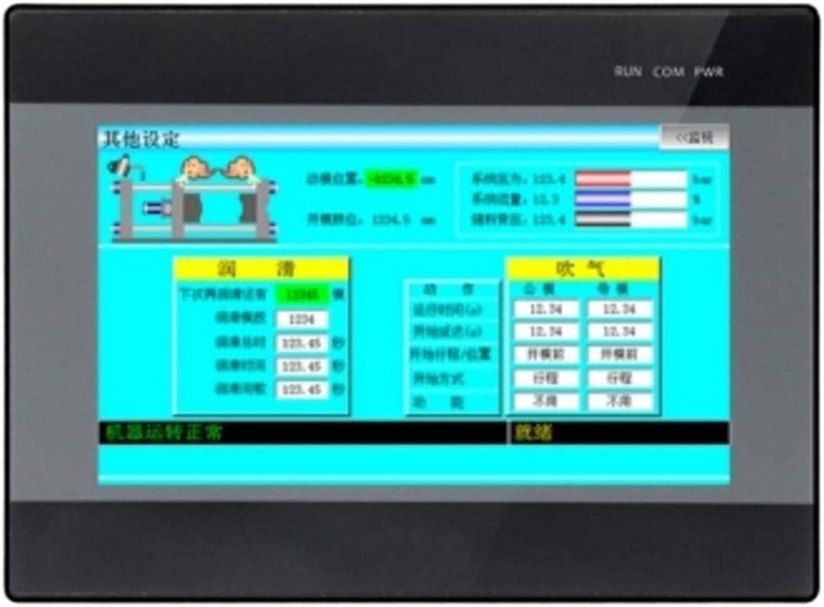
Figure 3: Example of a settings screen on the HMI display, demonstrating various input fields and display elements.
4.3 PLC Programming and Configuration
The integrated PLC can be programmed using compatible software via the PLC programming port. Refer to the specific PLC programming software manual for detailed instructions on creating and uploading ladder logic or other control programs. The HMI interface can be designed and uploaded via the HMI programming interface.
4.4 Monitoring and Control
Use the HMI display to monitor real-time process data, view alarms, and control connected machinery or systems. The specific screens and control functions will depend on the application program loaded onto the device.
5. Maintenance
Regular maintenance ensures the longevity and reliable operation of your HMI display.
- Cleaning: Gently wipe the screen and casing with a soft, dry, lint-free cloth. For stubborn marks, use a slightly damp cloth with a mild, non-abrasive cleaner. Avoid excessive moisture and harsh chemicals.
- Environmental Conditions: Ensure the operating environment remains within the specified temperature and humidity ranges to prevent damage.
- Connection Checks: Periodically inspect all wiring connections for looseness or corrosion. Re-tighten as necessary.
- Software Updates: Check the manufacturer's website for any available firmware or software updates for the HMI and PLC. Follow update instructions carefully.
6. Troubleshooting
This section provides solutions to common issues you might encounter.
| Problem | Possible Cause | Solution |
|---|---|---|
| Display does not power on. | No power supply; incorrect wiring; faulty power supply. | Check 24V DC power connection. Verify wiring polarity. Test power supply unit. |
| Touch screen unresponsive. | Screen calibration issue; physical damage; software glitch. | Attempt screen recalibration (if available in settings). Restart the unit. Contact support if persistent. |
| PLC not running (RUN light off). | No program loaded; PLC in STOP mode; hardware fault. | Ensure a valid program is loaded. Check PLC run switch position. Consult PLC programming software for diagnostics. |
| Communication error with external device. | Incorrect wiring; wrong communication settings (baud rate, parity); device address mismatch. | Verify RS485/RS232 wiring. Check communication parameters in HMI and external device. Ensure unique device addresses. |
7. Specifications
Detailed technical specifications for the MX3G-70C-48MT model.
| Feature | Detail |
|---|---|
| Model | MX3G-70C-48MT |
| Display Size | 7 inches |
| Analog Inputs (AD) | 5 (2 x 0-10V, 3 x 0-20mA) |
| Analog Outputs (DA) | 2 (0-20mA) |
| Digital Inputs (X) | 24 (X0-X27) |
| Digital Outputs (Y) | 24 Transistor (Y0-Y27), 4 pulse outputs (Y0-Y4) |
| Communication | MODBUS RTU, RS485, RS232 |
| Power Supply | 24V DC |
| Overall Dimensions | 210mm x 146mm x 36mm |
| Panel Cutout Size | 192mm x 138mm |
| Item Weight | 1.76 pounds |
| Manufacturer | SHIHUANI |
| Country of Origin | China |
Note: Package dimensions (1.18 x 0.79 x 0.39 inches) refer to the shipping package, not the unit itself. For precise installation, use the Overall Dimensions and Panel Cutout Size provided above.
8. Warranty and Support
For warranty information, technical support, or service inquiries, please contact your vendor or the manufacturer directly. Keep your purchase receipt and product model number handy for faster assistance.
Manufacturer: SHIHUANI
Model: MX3G-70C-48MT