DANOPLUS Ultrasonic Thickness Gauge
Ultrasonic Thickness Gauge Instruction Manual
Brand: DANOPLUS | Model: Ultrasonic Thickness Gauge
1. Product Overview
The DANOPLUS Ultrasonic Thickness Gauge is a high-precision instrument designed for accurately measuring the thickness of various materials. It is suitable for a wide range of applications, including measuring the thickness of steel, metal, ceramics, glass, and plastics. The device features an intuitive color display, data logging capabilities, and automatic calibration for precise and reliable measurements.
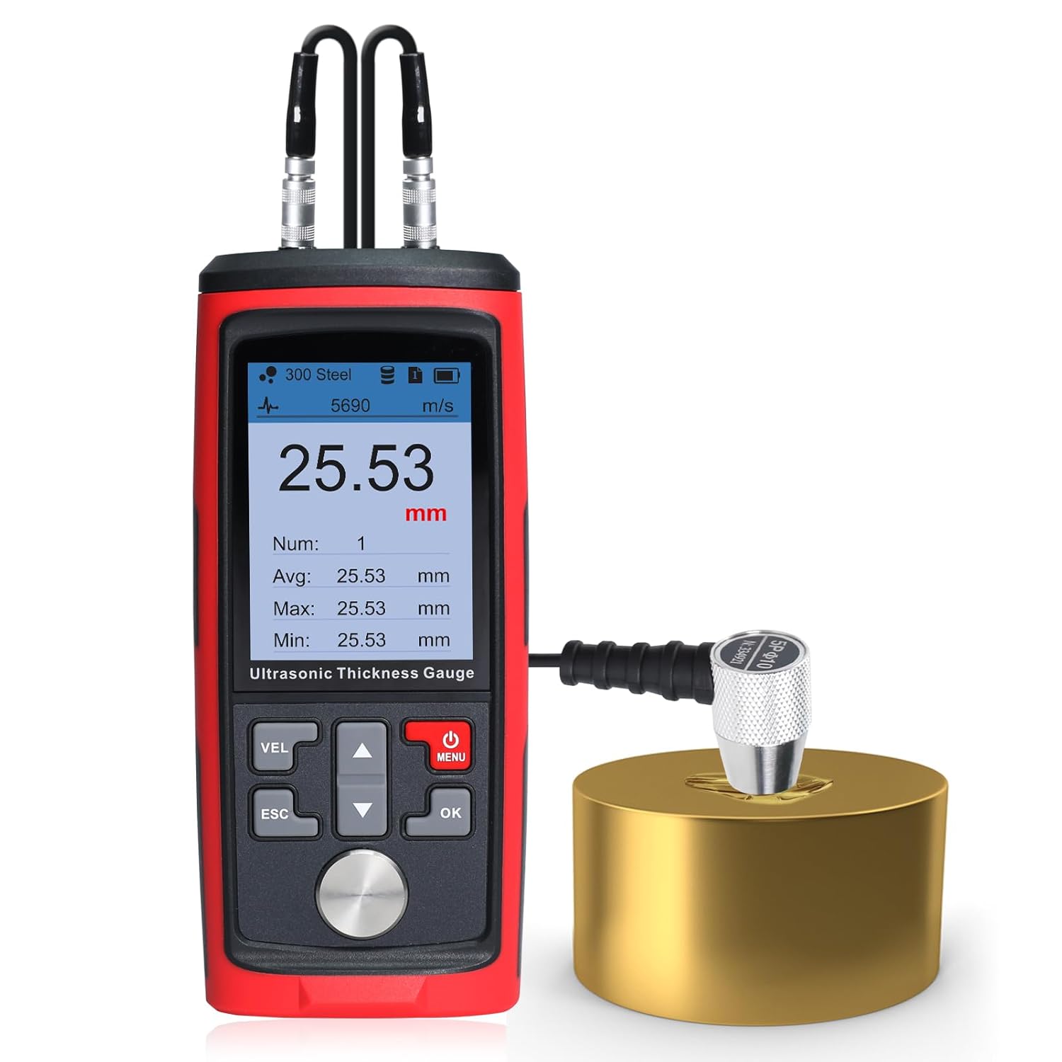
Image: The DANOPLUS Ultrasonic Thickness Gauge shown with its included 4mm calibration block, demonstrating its primary function.
2. What's in the Box
Upon opening the package, please verify that all the following components are present:
- 1x Thickness Meter
- 1x Sensor (Probe)
- 1x Coupling Agent
- 1x USB Cable
- Carrying Case

Image: All components included in the product package, neatly arranged within the carrying case.
3. Product Components
Familiarize yourself with the main parts of the Ultrasonic Thickness Gauge:

Image: A detailed diagram highlighting the various components of the thickness gauge, including the probe socket, display, control buttons, and USB port.
- Probe Socket: Connects the sensor probe to the main unit.
- Display: Intuitive color screen showing measurement values, settings, and status.
- Control Buttons: Includes VEL (Velocity), ESC (Escape), Up/Down arrows, MENU, and OK buttons for navigation and operation.
- USB Port: For charging the device.
- Calibration Sample: A built-in 4mm calibration block for accurate calibration.
- Probe: The transducer that emits and receives ultrasonic waves.
4. Setup
Follow these steps for initial setup and calibration:
- Connect the Probe: Securely connect the sensor probe to the probe sockets on the top of the main unit. Ensure a firm connection for accurate readings.
- Apply Coupling Agent: Apply a small amount of the provided coupling agent to the surface of the material to be measured, or directly to the probe's contact surface. This ensures proper ultrasonic wave transmission.
- Initial Calibration: The device comes with a built-in 4mm calibration block. Place the probe firmly on this block with coupling agent. The device will automatically calibrate, ensuring precise measurements. Refer to the display for confirmation of successful calibration.
Image: The thickness gauge performing an initial calibration using the integrated 4mm calibration block.
5. Operating Instructions
5.1 Taking Measurements
To take a measurement, ensure the probe is connected and coupling agent is applied. Press the probe firmly against the surface of the material. The thickness reading will appear on the display. The device supports MAX/MIN/AVE readings for comprehensive analysis.

Image: A user holding the thickness gauge and probe against a large metal surface to take a measurement.
5.2 Unit Switching
The device allows switching between millimeters (mm) and inches for versatile use. Navigate through the menu using the control buttons to select your preferred unit of measurement.
5.3 Data Logging
The ultrasonic testing equipment can store up to 1,500 data groups. It offers options for manual or automatic data recording, with 1-15 storage files, each capable of holding up to 100 data entries.

Image: The device display showing the data logging interface, with a table of recorded measurements.
5.4 Real-Time Alerts (Audible Alarm)
When the alarm function is enabled, the thickness meter's LCD display will change to a red indicator and emit a beep sound if the measured reading exceeds the set high or low limits.

Image: The thickness gauge display showing a red background, indicating that the measurement has exceeded a set limit and the audible alarm is active.
5.5 Sound Velocities of Common Materials
The accuracy of ultrasonic thickness measurement depends on the correct sound velocity setting for the material being tested. Below is a table of common materials and their approximate sound velocities:

Image: A table listing various materials and their corresponding sound velocities in meters per second (m/s), crucial for accurate gauge calibration.
| Material | Velocity (m/s) | Material | Velocity (m/s) |
|---|---|---|---|
| Aluminum | 6320 | Acetate resin | 2670 |
| Zinc | 4170 | Phosphor bronze | 3530 |
| Silver | 3600 | Turpentine | 4430 |
| Gold | 3240 | Glass | 5440 |
| Tin | 3230 | Incoloy alloy | 5720 |
| Iron/Steel | 5900 | Magnesium | 6310 |
| Brass | 4640 | Monel alloy | 6020 |
| Copper | 4700 | Nickle | 5630 |
| SUS | 5790 | Steel 4330(mild) | 5850 |
| Acrylic resin | 2730 | Steel 330 | 5660 |
| Water (20°C) | 1480 | Titanium | 6070 |
| Glycerinl | 1920 | Zirconium | 4650 |
| Soluble glass | 2350 | Nylon | 2620 |
6. Maintenance
Proper maintenance ensures the longevity and accuracy of your Ultrasonic Thickness Gauge.
- Cleaning: After each use, wipe the probe and the device's contact surface clean of any residual coupling agent using a soft, dry cloth. Do not use abrasive cleaners or solvents.
- Storage: Store the device and its accessories in the provided carrying case in a cool, dry place, away from direct sunlight and extreme temperatures.
- Battery Care: If the device will not be used for an extended period, ensure it is fully charged before storage and periodically recharge it to maintain battery health.
7. Troubleshooting
This section addresses common issues you might encounter.
- Unstable or Inaccurate Readings:
- Ensure sufficient coupling agent is applied between the probe and the material surface.
- Verify that the probe is held firmly and perpendicularly against the surface.
- Check for any debris or unevenness on the material surface or probe face.
- Recalibrate the device using the 4mm calibration block.
- Confirm the correct sound velocity is selected for the material being measured.
- Device Not Measuring on Plastic:
- This Ultrasonic Thickness Gauge is primarily designed for measuring metals and other dense materials. It may not provide accurate readings on certain plastics or other non-metallic materials due to differences in acoustic properties.
- No Reading Displayed:
- Check if the probe is properly connected to the device.
- Ensure the device battery is charged.
- Confirm adequate coupling agent is used.
- The material might be outside the measurable range (0.03~11.8 inches).
8. Specifications
Key technical specifications for the DANOPLUS Ultrasonic Thickness Gauge:
| Feature | Value |
|---|---|
| Measurement Range | 1.0~300.0mm (steel) |
| Data Storage | 1500 data sets |
| Operation Frequency | 5MHz/2.5MHz |
| Accuracy | ±(0.5%H+0.05)mm |
| Resolution | 0.01mm (1.00~99.99mm) / 0.1mm (100~300mm) |
| Pipe Lower Limit | 20x3mm (steel) |
| Sound Speed Measurement | 1000~9999m/s |
| Operating Temperature | 0~40°C (32~104°F) |
| Power Supply | 1000mAh 3.7V Li Battery |
| USB Charging | 5V 1A |
| Product Dimensions | 5.98 x 2.55 x 1.06 inches |
| Weight | 2.56 ounces |
| Manufacturer | DANOPLUS |
| ASIN | B0DH87P9BC |
9. Warranty and Support
This product is manufactured by DANOPLUS. For any support inquiries or warranty claims, please contact the manufacturer directly or refer to the seller's support information.
Optional protection plans may be available for purchase separately to extend coverage beyond the standard manufacturer's warranty. Please consult the retailer for details on available protection plans.
Ask a question about this manual
Ask about setup, troubleshooting, compatibility, parts, safety, or missing instructions. Manuals+ will review the question and use this page’s manual context to help answer it.