havcybin CT-8A
HOTRC CT-8A 8-Channel RC Transmitter and Receiver User Manual
Model: CT-8A
1. Introduction
This manual provides detailed instructions for the proper setup, operation, and maintenance of your HOTRC CT-8A 8-Channel RC Transmitter and Receiver system. Please read this manual thoroughly before using the product to ensure safe and efficient operation. This system is designed for controlling various RC models, including cars, boats, and tanks.
2. Product Overview
2.1 Key Features
- 8-Channel 2.4GHz System: Utilizes 2.4G frequency hopping technology for strong anti-interference performance and stable operation.
- Extended Range: Offers a ground control distance of up to 300 meters and an air control distance of up to 800 meters.
- 2.4-inch TFT Color Screen: Provides a clear display for parameter adjustments, including mix programming, curve setting, intelligent vehicle control, cruise control, and self-control protection.
- Gyro Function Receiver: The F-08AT receiver model includes an integrated gyro function for enhanced stability. (Note: Verify your specific receiver model upon receipt, as some packages may contain the F-08A without gyro.)
- Coaching Function: Supports teaching and training activities using a single data connection cable, allowing two remote controls to operate one RC model simultaneously.
- Multiple Charging Options: Supports USB charging, 2S 7.4V lithium batteries, 18650 batteries, and No. 5 (AA) batteries for flexible power supply.
- Ergonomic Design: Features a standard sponge wheel, electroplated hand wheel, high-grade PVC panel, and comfortable silicone strips for improved grip and control.
2.2 Transmitter Components
Familiarize yourself with the main components of the CT-8A transmitter:

Image: Overview of the HOTRC CT-8A transmitter, highlighting its various components such as the charging port, internal antenna, directional stick, operation panel, channel buttons, metal pendant, SWB/SWA channels, throttle trigger, one-hand control area, and battery compartments (18650, 5th battery, 2S lithium).
- Charging Port / Coach's Mouth / Upgrade Port: USB Type-C interface for charging, coaching function, and firmware upgrades.
- Internal Antenna: For 2.4GHz signal transmission.
- Directional Stick: Controls steering.
- Operation Panel: Includes the 2.4-inch TFT color screen and navigation buttons.
- Channel Buttons (CH1-CH8): For assigning and controlling various functions.
- Metal Pendant: Red CNC metal pendant, can be used with a cell phone holder.
- SWB/SWA Channels: Auxiliary switches for additional functions.
- Throttle Trigger: Controls acceleration/deceleration.
- One-Hand Control: Ergonomic design for comfortable single-handed operation.
- Battery Compartments: Dedicated slots for 18650, 5th (AA), and 2S lithium batteries.
2.3 Receiver (F-08A / F-08AT)
The receiver connects to your RC model's electronic speed controller (ESC) and servos. It receives signals from the transmitter to control the model.

Image: The HOTRC F-08A receiver, showing its 8 PWM channels, input voltage range (4V-9V DC), and bind button. The F-08AT model includes an integrated gyro.
- Channels: 8 PWM channels for connecting servos and ESCs.
- Input Voltage: DC 3.5V-9V.
- Bind Button: Used for pairing the receiver with the transmitter.
- Gyro Function (F-08AT only): Provides stability assistance for your RC model.
3. Setup
3.1 Battery Installation and Charging
The CT-8A transmitter supports multiple battery types. Ensure correct polarity when installing batteries.
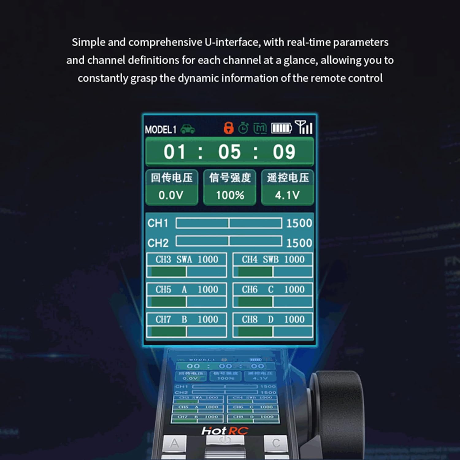
Image: Diagram illustrating the three power supply methods for the HOTRC CT-8A transmitter: 18650 battery, 2S lithium battery, and four No. 5 (AA) batteries. It also shows the Type-C interface for charging.
- Open Battery Compartment: Locate and open the battery compartment cover on the back of the transmitter.
- Install Batteries: Insert your chosen battery type (18650, 2S 7.4V LiPo, or 4x AA batteries) according to the polarity indicators.
- Close Compartment: Securely close the battery compartment cover.
- Charging: Connect a USB Type-C cable to the charging port on the transmitter to charge 18650 batteries (if installed). For 2S LiPo batteries, use an external LiPo charger.
Note: Batteries are not included with the product and must be purchased separately.
3.2 Binding Transmitter and Receiver
To establish communication between the transmitter and receiver, they must be bound.
- Power Off Transmitter: Ensure the CT-8A transmitter is powered off.
- Connect Receiver Power: Connect the receiver to a power source (e.g., ESC with BEC or a separate receiver battery). The receiver's LED should flash, indicating it's in binding mode or waiting for a signal.
- Press Bind Button: While the receiver is powered on, press and hold the "BIND" button on the receiver.
- Power On Transmitter: While still holding the bind button on the receiver, power on the CT-8A transmitter.
- Release Bind Button: Once the receiver's LED turns solid (or stops flashing in a specific pattern), release the bind button. This indicates a successful bind.
- Test Connection: Power cycle both the transmitter and receiver. Test the controls to ensure proper functionality.
4. Operating Instructions
4.1 Basic Controls
- Steering: Use the directional stick (wheel) to control the left and right movement of your model.
- Throttle: Use the throttle trigger to control forward and reverse movement, as well as speed. Pull the trigger for forward, push for reverse/brake.
4.2 Advanced Functions and Screen Interface
The 2.4-inch TFT color screen provides access to various settings and real-time data.

Image: The HOTRC CT-8A transmitter's screen interface, displaying real-time parameters such as model number, timer, battery voltage, signal strength, and channel definitions (CH1-CH8) with their current values.
- Real-time Parameters: The screen displays current model settings, battery voltage, signal strength, and channel values.
- Navigation: Use the buttons below the screen to navigate through menus and adjust settings. Refer to the on-screen prompts for specific operations.
- Mix Programming: Configure custom mixing functions between channels for complex model control.
- Curve Setting: Adjust the response curves for throttle and steering to fine-tune control feel.
- Intelligent Vehicle Control: Access specific settings for vehicle stability and performance.
- Cruise Control: Maintain a set speed for your model.
- Self-Control Protection: Implement safety features to prevent unintended movements.
- Locking Function: To prevent accidental operation, the remote control can be locked.
- Automatic Shutdown: The transmitter will automatically shut down after 15 minutes of inactivity to conserve battery life.
4.3 Throttle Trigger Adjustments
The throttle trigger offers adjustable settings for personalized control.

Image: Close-up view of the HOTRC CT-8A transmitter's throttle trigger, showing adjustment points for the trigger spring force and the front and rear positions of the trigger. The trigger also features a ripple texture to prevent slipping.
- Adjusting Trigger Spring Force: Use the designated screw or mechanism to increase or decrease the resistance of the throttle trigger.
- Adjusting Trigger Position: Modify the front and rear travel limits of the throttle trigger for optimal comfort and control.
4.4 Coaching Function
The coaching function allows two transmitters to control one model, ideal for training or shared experiences.

Image: Illustration of the HOTRC CT-8A coaching function, showing two individuals using separate transmitters connected via a data cable to control a single RC car. This enables teaching and training scenarios.
- Connect Data Cable: Use a standard data connection cable to link the "Coach's Mouth" (Type-C port) of both transmitters.
- Configure Transmitters: Follow the on-screen instructions on both transmitters to activate and configure the coaching mode. One transmitter will act as the master, and the other as the slave.
- Operation: The master transmitter has primary control, while the slave can take over control when enabled by the master, typically by holding a specific button or switch.
5. Maintenance
- Cleaning: Use a soft, dry cloth to clean the transmitter and receiver. Avoid using solvents or harsh chemicals.
- Storage: Store the system in a cool, dry place away from direct sunlight and extreme temperatures. Remove batteries if storing for extended periods.
- Battery Care: Follow manufacturer guidelines for charging and discharging your chosen battery types. Do not overcharge or over-discharge LiPo batteries.
- Rocker Assembly: The rocker assembly features 4 ball bearings and a potentiometer designed for durability. No user maintenance is typically required for these internal components.

Image: Detailed view of the HOTRC CT-8A transmitter's rocker assembly, showing the internal structure with four ball bearings (Bearing I, II, III, IV) and a potentiometer. This design ensures smooth, accurate control and a long lifespan.
6. Troubleshooting
| Problem | Possible Cause | Solution |
|---|---|---|
| Transmitter does not power on. | Low or dead batteries; incorrect battery installation. | Check battery charge level and replace/recharge if necessary. Verify correct battery polarity. |
| Receiver LED not solid after binding attempt. | Binding failed; transmitter too far from receiver; interference. | Repeat the binding procedure. Ensure transmitter and receiver are close during binding. Check for other 2.4GHz devices nearby. |
| Loss of control or short range. | Low transmitter/receiver battery; antenna obstruction; excessive interference. | Ensure batteries are fully charged. Position receiver antenna correctly and away from metal. Avoid operating in areas with strong Wi-Fi or other 2.4GHz signals. |
| Controls are reversed or erratic. | Incorrect servo direction settings (reverse); trim settings off. | Adjust servo reverse settings in the transmitter menu. Reset trim settings to neutral. |
7. Specifications
| Model Type | Car, Boat, Tank |
| Channels | 8CH |
| RF Range | 2.4Ghz ISM |
| RF Power | ≤100mW |
| Modulation | GFSK |
| Spread Spectrum | FHSS |
| Reaction Speed | PWM≤20ms |
| RF Distance (Ground) | Up to 300m |
| RF Distance (Air) | Up to 800m |
| Receive Sensitivity | -97dbm |
| Transmit Power Consumption | ≈160MA-300MA |
| Transmitter Voltage | DC 3.7-9V |
| Receiver Voltage | DC 3.5V-9V |
| Material | Plastic |
| Product Dimensions (Transmitter) | 10.16 x 7.62 x 5.08 cm |
| Product Weight (Transmitter) | 458 g |
8. Warranty and Support
Specific warranty information for the HOTRC CT-8A transmitter and receiver system is not provided in the product details. Please refer to the retailer or manufacturer's website for warranty terms and conditions.
For technical support or further assistance, please contact your point of purchase or the official HOTRC support channels.
Ask a question about this manual
Ask about setup, troubleshooting, compatibility, parts, safety, or missing instructions. Manuals+ will review the question and use this page’s manual context to help answer it.