1. Introduction
This manual provides comprehensive instructions for the installation, operation, and maintenance of your JMT H61M-I Mini ITX Motherboard. This motherboard is designed for desktop computers, featuring an LGA1155 CPU socket, two DDR3 RAM slots supporting up to 16GB dual-channel memory, and an M.2 slot compatible with NVMe/NGFF SSDs. Please read this manual carefully before proceeding with installation to ensure proper setup and optimal performance.
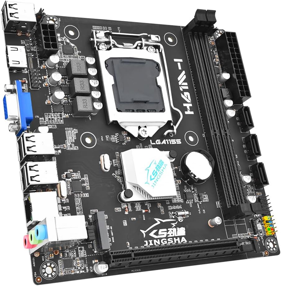
Image 1.1: Overview of the JMT H61M-I Mini ITX Motherboard. This image displays the compact form factor and primary components including the CPU socket, RAM slots, and various connectors.
2. Setup and Installation
Follow these steps to correctly install your JMT H61M-I motherboard and its components.
2.1 Motherboard Layout
Image 2.1: Detailed layout of the H61M-I motherboard, indicating the location of key components and connectors such as the CPU socket, DDR3 slots, M.2 slot, SATA ports, and various headers.
- CPU Socket (LGA1155): Located centrally for Intel LGA1155 processors.
- DDR3 Slots: Two slots for DDR3 memory modules.
- M.2 Slot: Supports NVMe/NGFF M.2 SSDs.
- PCI-E X16 Slot: For graphics cards or other expansion cards.
- SATA 2.0 Ports: Three ports for connecting storage devices.
- USB 2.0 Headers: For front panel USB ports.
- Power Connectors: 24-pin ATX and 8-pin ATX_12V for power supply.
- Front Panel Headers: For power button, reset button, HDD LED, power LED, and front audio.
- I/O Panel: Includes HD, VGA, USB 2.0, Gigabit Ethernet, and audio ports.
2.2 Component Installation
- CPU Installation:
- Open the CPU socket lever.
- Carefully align the CPU with the socket, ensuring the notches match.
- Gently place the CPU into the socket without forcing it.
- Close the lever to secure the CPU.
- Apply thermal paste and install the CPU cooler.
- RAM Installation:
- Open the clips on both ends of the DDR3 memory slots.
- Align the memory module with the slot, ensuring the notch on the module matches the key in the slot.
- Press down firmly on both ends of the memory module until the clips snap into place.
- M.2 SSD Installation:
- Locate the M.2 slot on the motherboard.
- Insert the M.2 SSD into the slot at an angle.
- Gently push down the SSD and secure it with the provided screw.
- Graphics Card Installation (Optional):
- Locate the PCI-E X16 slot.
- Align your graphics card with the slot and press down firmly until it is fully seated.
- Secure the card to your PC case with a screw.
- SATA Device Connection:
- Connect SATA data cables from your storage devices (HDD/SSD) to the SATA 2.0 ports on the motherboard.
- Ensure power cables from the PSU are connected to your storage devices.
- Power Supply Connection:
- Connect the 24-pin ATX power connector from your power supply unit (PSU) to the main power socket on the motherboard.
- Connect the 8-pin ATX_12V power connector from your PSU to the CPU power socket.
- Front Panel Connections:
- Refer to the motherboard layout diagram (Image 2.1) and your PC case manual to connect the front panel headers (Power SW, Reset SW, HDD LED, Power LED, F_AUDIO, USB 2.0).
3. Operating Instructions
Once all components are installed and connected, you can power on your system.
- Initial Power On: After connecting all necessary cables, press the power button on your PC case. The system should initiate the Power-On Self-Test (POST).
- BIOS/UEFI Access: During the initial boot sequence, repeatedly press the DEL or F2 key (common keys, may vary) to enter the BIOS/UEFI setup utility. Here you can configure boot order, system time, and other advanced settings.
- Operating System Installation: Insert your operating system installation media (USB drive or DVD) and follow the on-screen prompts to install your preferred operating system. Ensure the boot order in BIOS/UEFI is set to prioritize your installation media.
- Driver Installation: After installing the operating system, install the necessary drivers for the motherboard chipset, graphics card, audio, and network. These are typically provided on a CD/DVD with your components or can be downloaded from the manufacturer's websites.
4. Maintenance
Regular maintenance helps ensure the longevity and stable performance of your motherboard.
- Dust Removal: Periodically clean dust from the motherboard and components using compressed air. Ensure the system is powered off and unplugged before cleaning.
- BIOS/UEFI Updates: Check the JMT website for any available BIOS/UEFI updates. Updates can improve compatibility, stability, and performance. Follow the manufacturer's instructions carefully when performing updates.
- Driver Updates: Keep your system drivers updated. Outdated drivers can lead to performance issues or instability.
- Cable Management: Ensure all cables are neatly routed to improve airflow and prevent accidental disconnections.
5. Troubleshooting
If you encounter issues, refer to the following common troubleshooting steps.
- No Power:
- Verify that the 24-pin ATX and 8-pin ATX_12V power connectors are securely seated.
- Check if the power supply unit (PSU) is switched on and functioning correctly.
- Ensure the front panel power button cable is correctly connected to the motherboard header.
- No Display/No POST (Power-On Self-Test):
- Ensure the monitor is connected to the correct display output (motherboard integrated graphics or discrete graphics card).
- Reseat the RAM modules. Try booting with one RAM module at a time if you have multiple.
- Reseat the CPU and check for bent pins in the socket.
- If using a discrete graphics card, reseat it in the PCI-E slot.
- Clear the CMOS (Complementary Metal-Oxide-Semiconductor) by removing the CMOS battery for a few minutes or using the CLR_CMOS header if available (refer to Image 2.1 for location).
- System Instability/Crashes:
- Check CPU and GPU temperatures to ensure they are within safe operating limits.
- Verify that all drivers are up to date.
- Run memory diagnostic tools to check for faulty RAM.
- Ensure the power supply is sufficient for all installed components.
- Operating System Not Booting:
- Check the boot order in BIOS/UEFI to ensure the correct drive is selected.
- Verify that the operating system drive (HDD/SSD) is properly connected and detected by the BIOS/UEFI.
6. Specifications
Detailed technical specifications for the JMT H61M-I Motherboard.
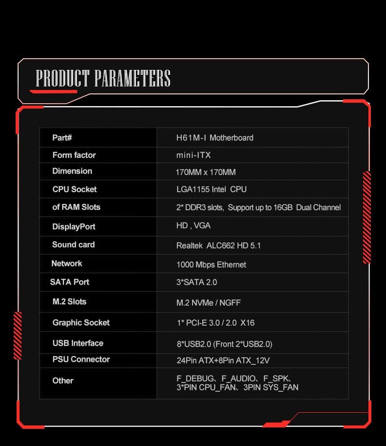
Image 6.1: Official product parameters table for the H61M-I motherboard, detailing various technical specifications.
| Feature | Specification |
|---|---|
| Part No. | H61M-I Motherboard |
| Form Factor | Mini-ITX |
| Dimension | 170MM x 170MM |
| CPU Socket | LGA1155 CPU (Intel LGA1155 Chipset Type) |
| RAM Slots | 2* DDR3 slots, Support up to 16GB Dual Channel |
| Display Port | HD, VGA |
| Sound Card | ALC662 HD 5.1 |
| Network | 1000 Mbps Ethernet |
| SATA Port | 3*SATA 2.0 |
| M.2 Slots | M.2 NVMe / NGFF |
| Graphic Socket | 1*PCI-E 3.0/2.0 X16 |
| USB Interface | 8*USB2.0 (Front 2*USB2.0) |
| PSU Connector | 24Pin ATX + 8Pin ATX_12V |
| Other Headers | F_DEBUG, F_AUDIO, F_SPK, 3*PIN CPU_FAN, 3PIN SYS_FAN |
| Package Dimensions | 7.87 x 4.72 x 3.94 inches |
| Item Weight | 1.39 pounds |
| Manufacturer | JMT |
| Date First Available | September 16, 2024 |
| Compatible Devices | Desktop |
| RAM Memory Technology | DDR3 |
| Compatible Processors | 1 (LGA1155) |
| Memory Clock Speed | 16.0 (likely 1600MHz for DDR3) |
| Platform | Windows 10 |
| Memory Slots Available | 2 |
7. Warranty and Support
For warranty information and technical support, please refer to the official JMT website or contact your retailer.
- Warranty: Specific warranty terms and conditions may vary by region and retailer. Please retain your proof of purchase for warranty claims.
- Technical Support: For further assistance, driver downloads, or BIOS updates, visit the official JMT support page or the JMT Store on Amazon: JMT Store.