1. Introduction
This manual provides essential information for the safe and efficient installation, operation, and maintenance of the FPBIGCHA P40 Series Monoblock Directional Valve. Please read this manual thoroughly before using the product to ensure proper function and to prevent damage or injury.
The FPBIGCHA P40 Series Monoblock Directional Valve is designed for controlling the flow of hydraulic fluid in various applications, specifically for operating double-acting cylinders. This particular model features detent control, allowing the spool to remain in a selected position until manually returned to neutral.
2. Safety Information
WARNING:
Failure to follow these safety instructions may result in serious injury, death, or property damage.
- Always ensure the hydraulic system is depressurized before performing any installation, maintenance, or repair work.
- Wear appropriate personal protective equipment (PPE), including safety glasses and gloves, when working with hydraulic systems.
- Ensure all connections are secure and free from leaks. High-pressure fluid can cause severe injury.
- Do not exceed the maximum operating pressure specified for this valve.
- Only qualified personnel should install and service hydraulic components.
- Keep hands and clothing clear of moving parts and pressurized lines.
3. Product Overview
The FPBIGCHA P40 Series Monoblock Directional Valve is a robust component designed for precise hydraulic control. Key features include:
- Hydraulic control valve for operating double-acting cylinders.
- Standard double-acting spools with detent control, allowing the spool to hold its position.
- Constructed from durable casting material for high pressure applications.
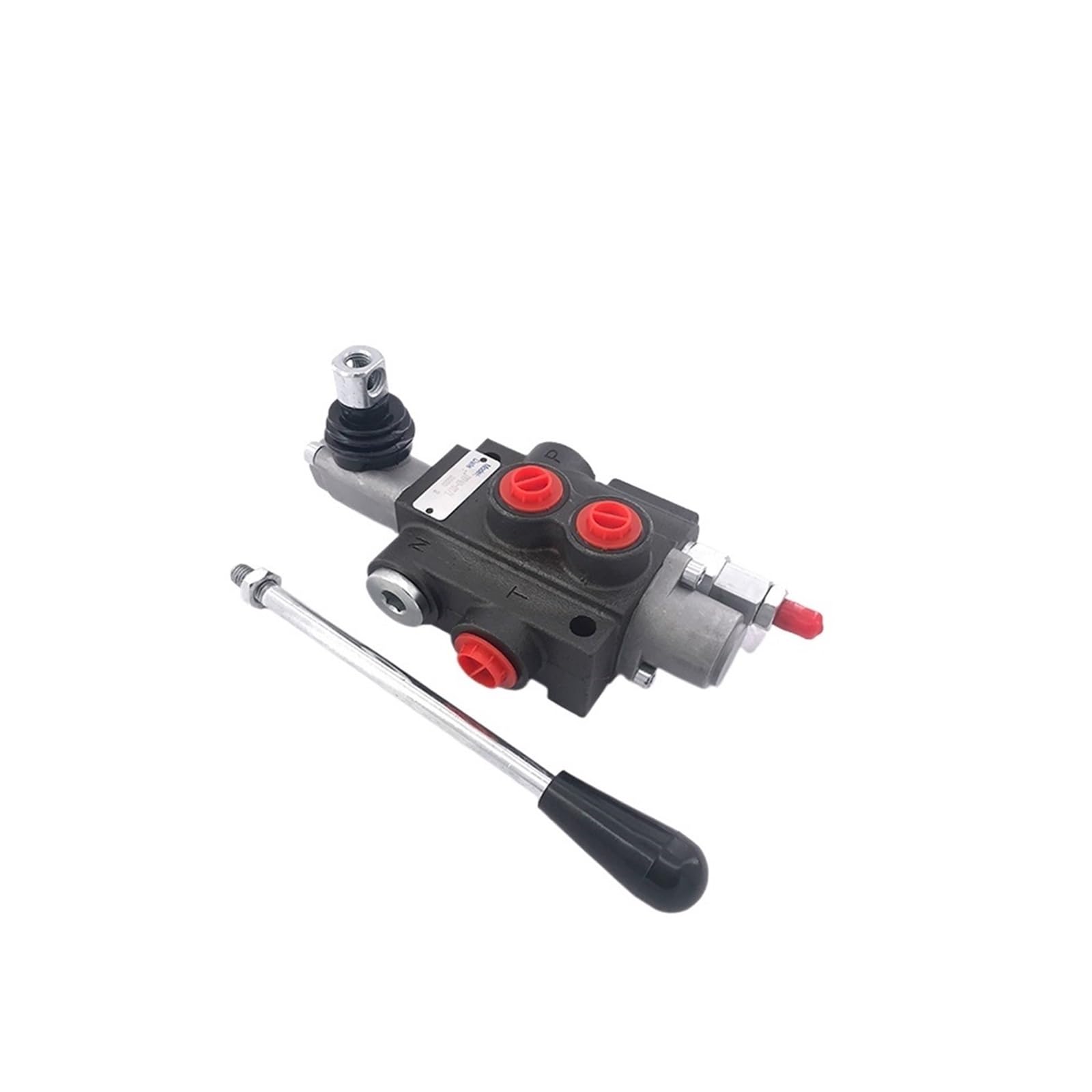
Figure 3.1: Front view of the FPBIGCHA P40 Series Monoblock Directional Valve with the control handle attached.

Figure 3.2: Top view of the valve, illustrating the pressure (P), tank (T), and work ports (A, B, N).
4. Setup and Installation
Proper installation is crucial for the performance and longevity of the valve. Refer to your hydraulic system's schematic for specific port connections.
- Mounting: Securely mount the valve to a stable surface using appropriate fasteners. Ensure there is adequate clearance for the control handle and hydraulic lines.
- Port Connections:
- Connect the pressure line from the pump to the 'P' port.
- Connect the return line to the hydraulic reservoir to the 'T' (Tank) port.
- Connect the cylinder lines to the 'A' and 'B' work ports. For multi-spool valves (e.g., 2P40, 3P40, 4P40), each spool will have its own 'A' and 'B' ports.
- Ensure all connections are tight and sealed to prevent leaks. Use appropriate thread sealant if necessary.
- System Bleeding: After installation, slowly cycle the hydraulic system to bleed air from the lines and cylinders. Monitor fluid levels and pressure.
- Initial Check: Verify that all components are functioning correctly and that there are no leaks under operating pressure.

Figure 4.1: Side view showing the model identification plate and port configurations for connection.
5. Operating Instructions
The P40 Series valve with detent control allows for sustained operation in a selected position without continuous manual holding.
- Neutral Position: When the control handle is in the central position, the valve is in neutral. In this position, fluid typically flows through the valve back to the tank (open center) or is blocked (closed center), depending on the valve configuration.
- Actuating a Cylinder:
- To extend a double-acting cylinder, move the control handle to one of the detent positions (e.g., forward). The spool will lock into this position, directing fluid to extend the cylinder.
- To retract a double-acting cylinder, move the control handle to the opposite detent position (e.g., backward). The spool will lock, directing fluid to retract the cylinder.
- Returning to Neutral: To stop cylinder movement, manually push or pull the control handle back to the central neutral position. The detent mechanism will release, and the spool will center.
- Monitoring: Always monitor the cylinder's movement and the system's pressure during operation. Do not force the handle if resistance is encountered.
6. Maintenance
Regular maintenance ensures optimal performance and extends the lifespan of your hydraulic valve.
- Fluid Quality: Ensure the hydraulic fluid is clean and free from contaminants. Contaminated fluid is a leading cause of valve failure. Follow the hydraulic system manufacturer's recommendations for fluid type and change intervals.
- Filter Replacement: Regularly inspect and replace hydraulic filters as recommended by your system's manufacturer.
- Leak Inspection: Periodically inspect all hydraulic lines and connections for leaks. Tighten any loose fittings immediately.
- Visual Inspection: Check the valve body for any signs of damage, corrosion, or excessive wear.
- Control Handle: Ensure the control handle operates smoothly and the detent mechanism engages and disengages correctly. Lubricate pivot points if necessary.
7. Troubleshooting
This section provides solutions to common issues. For problems not listed here, contact qualified service personnel.
| Problem | Possible Cause | Solution |
|---|---|---|
| Cylinder does not move or moves slowly. | Low hydraulic fluid level, clogged filter, pump malfunction, valve spool stuck, air in system. | Check fluid level and add if necessary. Replace filter. Inspect pump. Check for obstructions in valve. Bleed air from system. |
| Fluid leaks from valve or connections. | Loose fittings, damaged seals/O-rings, cracked housing. | Tighten connections. Replace damaged seals/O-rings. Replace valve if housing is cracked. |
| Valve handle is stiff or difficult to move. | Contamination in valve, damaged spool, lack of lubrication. | Flush system. Inspect spool for damage. Lubricate handle pivot points. |
| Detent control does not hold position. | Worn detent mechanism components. | Inspect and replace worn detent components. |
8. Specifications
The following specifications apply to the FPBIGCHA P40 Series Monoblock Directional Valve (P40-F-O Detent Control):
- Model Number: P40
- Material: Casting
- Power: Hydraulic
- Standard or Nonstandard: Standard
- Pressure: High Pressure
- Item Weight: 17.64 pounds (approximately 8 kg)
- Package Dimensions: 1.18 x 0.79 x 0.39 inches (approximately 3 x 2 x 1 cm) - Note: These package dimensions seem unusually small for the item weight. Please verify actual product dimensions.
- Assembly Required: No (for the valve itself)
- Number of Pieces: 1 (valve unit)
Note: Specifications are subject to change without notice. Always refer to the product label for the most accurate information.
9. Warranty Information
FPBIGCHA products are manufactured to high-quality standards. Specific warranty terms and conditions may vary by region and retailer. Please retain your proof of purchase for any warranty claims.
For detailed warranty information, please contact your point of purchase or the manufacturer directly.
10. Support and Contact
If you require technical assistance, have questions regarding installation, operation, or maintenance, or need to report a product issue, please contact your supplier or the manufacturer.
When contacting support, please have your product model number (P40) and purchase details readily available.