
1. Introduction
This manual provides detailed instructions for the safe and efficient use of the WPTGODGB TOMPD-63LW Smart Switch 63A. This device integrates voltage, current, and leakage protection with energy metering capabilities, functioning as a smart circuit breaker and timer. Please read this manual thoroughly before installation and operation.
2. Safety Information
WARNING: Electrical installation should only be performed by qualified personnel. Failure to follow these instructions may result in electric shock, fire, or serious injury.
- Ensure power is disconnected before installation or maintenance.
- Verify correct wiring connections (Input/Output, Neutral/Live).
- Do not operate the device if it is damaged.
- Keep the device away from water and excessive humidity.
3. Product Overview
The TOMPD-63LW is a multi-function protector designed to monitor and protect electrical circuits. It features a digital display for real-time readings and control buttons for configuration.
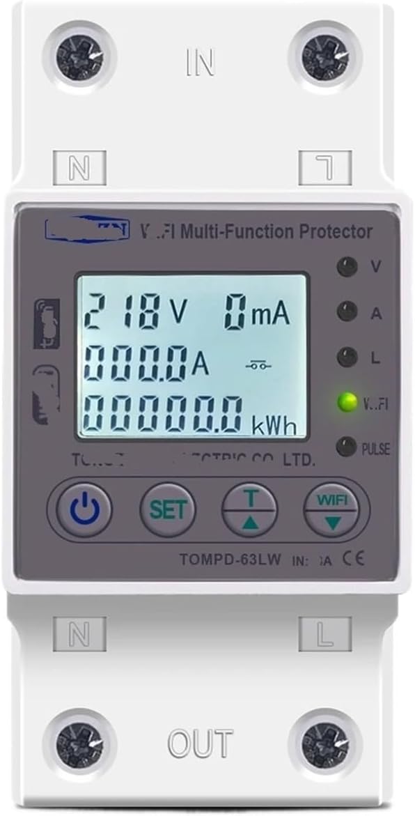
Figure 1: Front view of the WPTGODGB TOMPD-63LW Smart Switch 63A. The device features an LCD screen displaying voltage (V), current (A), and energy consumption (kWh). Below the screen are control buttons: Power, SET, Up (T), and Down (WiFi). Input terminals (IN) are at the top, and output terminals (OUT) are at the bottom, with Neutral (N) and Live (L) connections clearly marked.
3.1. Components and Display
- Digital Display: Shows real-time voltage (V), current (A), leakage current (mA), and energy consumption (kWh).
- Control Buttons:
- Power Button (⏻): Turns the device on/off or confirms settings.
- SET Button: Enters settings mode and navigates through parameters.
- Up Button (T): Adjusts values upwards or selects options.
- Down Button (WiFi): Adjusts values downwards or initiates WiFi pairing.
- Indicator Lights: V (Voltage), A (Current), L (Leakage), V..FI (WiFi/Status), PULSE (Energy Pulse).
- Input/Output Terminals: Clearly marked 'IN' at the top and 'OUT' at the bottom for Neutral (N) and Live (L) connections.
4. Setup and Installation
Proper installation is critical for the safe and effective operation of the Smart Switch. Ensure all local electrical codes are followed.
- Power Disconnection: Before beginning any wiring, ensure the main power supply to the circuit is completely disconnected at the breaker panel.
- Mounting: Mount the device securely within an appropriate electrical enclosure or on a DIN rail.
- Wiring Connections:
- Connect the incoming Live (L) wire to the 'L IN' terminal at the top.
- Connect the incoming Neutral (N) wire to the 'N IN' terminal at the top.
- Connect the outgoing Live (L) wire to the 'L OUT' terminal at the bottom.
- Connect the outgoing Neutral (N) wire to the 'N OUT' terminal at the bottom.
- Ensure all connections are tight and secure to prevent loose contacts and overheating.
- Power Restoration: Once all wiring is complete and verified, restore power to the circuit. The device display should illuminate.
5. Operating Instructions
5.1. Basic Operation
- Power On/Off: Press the Power button (⏻) briefly to toggle the output power.
- Display Readings: The default display cycles through Voltage (V), Current (A), and Energy Consumption (kWh). Leakage current (mA) may also be displayed.
5.2. Parameter Settings
To adjust protection parameters, follow these steps:
- Enter Settings: Press and hold the SET button for approximately 3-5 seconds until the display changes to a setting menu.
- Navigate Parameters: Briefly press the SET button to cycle through adjustable parameters:
- Undervoltage Protection (140V-210V, default 170V)
- Overvoltage Protection (225V-295V, default 265V)
- Overcurrent Protection (1A-63A, default 40A)
- Leakage Current Protection (Adjustable)
- Reconnection Time (Delayed opening time: 1s-500s, default 30s)
- Voltage/Current/kW Calibration (-9.9% - 9.9%)
- Action Time (1-30s, default 1s)
- Adjust Values: Use the Up (T) and Down (WiFi) buttons to increase or decrease the selected parameter value.
- Save Settings: After adjusting a parameter, briefly press the Power button (⏻) to confirm and save the setting. Continue pressing SET to move to the next parameter, or press and hold SET to exit settings mode.
5.3. WiFi Pairing (if applicable)
To connect the device to a WiFi network for remote monitoring and control (if supported by the specific model and app):
- Press and hold the Down (WiFi) button until the WiFi indicator (V..FI) starts blinking rapidly.
- Follow the instructions in the accompanying mobile application to complete the pairing process.
6. Maintenance
- Cleaning: Disconnect power before cleaning. Use a soft, dry cloth to wipe the device. Do not use liquid cleaners or solvents.
- Regular Checks: Periodically inspect wiring connections for tightness and signs of wear or damage.
- Firmware Updates: If available through the mobile application, ensure firmware is kept up-to-date for optimal performance and security.
7. Troubleshooting
| Problem | Possible Cause | Solution |
|---|---|---|
| Device not powering on. | No power supply; incorrect wiring; device fault. | Check main power supply. Verify wiring connections. Contact support if fault persists. |
| Output power trips frequently. | Overvoltage, undervoltage, overcurrent, or leakage detected. | Check connected load for faults. Review and adjust protection parameters if necessary. |
| WiFi connection fails. | Incorrect WiFi password; device too far from router; router issues. | Ensure correct WiFi credentials. Move device closer to router. Restart router. |
| Display shows abnormal readings. | Calibration error; sensor fault. | Perform voltage/current/kW calibration. Contact support if issue persists. |
8. Specifications
- Model: TOMPD-63LW
- Protection Types: Overvoltage, Undervoltage, Overcurrent, Leakage Current
- Undervoltage Protection Range: 140V-210V (adjustable, default 170V)
- Overvoltage Protection Range: 225V-295V (adjustable, default 265V)
- Overcurrent Protection Range: 1A-63A (adjustable, default 40A)
- Reconnection Time (Delayed Opening): 1s-500s (default 30s)
- Voltage/Current/kW Calibration: -9.9% - 9.9%
- Action Time: 1-30s (default 1s)
- Power Consumption: Less than 2W
- Display: White Background LCD
- Dimensions: Approximately 1.18 x 0.79 x 0.39 inches (Package Dimensions, actual device may vary slightly)
- Weight: Approximately 1.76 ounces
- Manufacturer: WPTGODGB
9. Warranty and Support
For warranty information and technical support, please refer to the documentation provided with your purchase or contact your retailer. Keep your proof of purchase for warranty claims.
For further assistance, visit the WPTGODGB official website or contact their customer service department.