RATTMMOTOR DM800
RATTMMOTOR DM800 5 Axis Standalone CNC Motion Offline Controller User Manual
Model: DM800
1. Introduction
This manual provides comprehensive instructions for the installation, operation, and maintenance of the RATTMMOTOR DM800 5 Axis Standalone CNC Motion Offline Controller. The DM800 is designed for precise control of CNC equipment without requiring a dedicated computer connection during operation.

Figure 1: RATTMMOTOR DM800 Hand Control System and Main Controller Unit.
This image displays the complete RATTMMOTOR DM800 system, including the handheld control unit with its display, buttons, and MPG dial, connected via a cable to the main controller unit. The main controller unit features various ports for connectivity.
Key features of the DM800 include:
- PC-less operation: G-code files can be loaded directly via a USB stick.
- Ethernet communication between the hand control and the main unit.
- Support for 5-axis stepping systems with a 460KHz pulse output per axis.
- Integrated ARM motion control chip for reliable performance.
- 20-port optically isolated input interface and 12-port optically isolated output interface.
- Built-in SD card for storage and a 3.8-inch TFT screen for user interaction.
- Suitable for various CNC applications including plasma cutting, flame cutting, woodworking, engraving, and automated welding.
2. Technical Specifications
| Feature | Specification |
|---|---|
| Model | DM800 |
| Supported Axes | 5-axis stepping system |
| Pulse Output Frequency | 460KHz per axis |
| Input Interface | 20-port optically isolated |
| Output Interface | 12-port optically isolated |
| Power Input (Main Device) | 24VDC, current > 1A |
| Display | 3.8-inch TFT screen |
| User Keys | 16 |
| Hand Control Dimensions | 208mm x 132mm x 32mm (8.19"L x 5.2"W x 1.26"H) |
| Host System Dimensions | 142mm x 100mm x 42mm |
| Item Weight | 3 pounds |
| Material | Plastic |
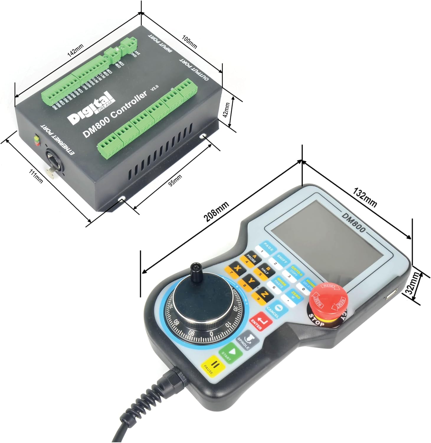
Figure 2: Physical dimensions of the DM800 hand control unit and the main controller unit.
This image provides detailed measurements for both the handheld controller (208mm length, 132mm width, 32mm height) and the main controller unit (142mm length, 100mm width, 42mm height), illustrating their compact sizes.
3. Included Components
The RATTMMOTOR DM800 package typically includes the following items:
- DM800 Hand Control Unit with integrated MPG and E-Stop button.
- DM800 Main Controller Unit (V2.0).
- Connection cable for hand control to main unit.
- Input and Output port connectors (DB9 type).
- USB stick (for G-code file transfer).

Figure 3: Close-up view of the DM800 hand control unit, highlighting the MPG dial and USB port.
This image provides a detailed view of the handheld controller, showing the Manual Pulse Generator (MPG) dial for precise axis movement and a USB port, typically used for loading G-code files.
4. Setup and Wiring
Proper setup and wiring are crucial for the safe and effective operation of the DM800 controller. Refer to the wiring diagrams below for detailed connection instructions.
4.1 Main Controller Unit Overview

Figure 4: DM800 Main Controller Unit with labeled ports.
This diagram illustrates the various ports on the DM800 main controller unit. Key ports include the Ethernet port (1), stepper motor ports (2-6), spindle port (7), output port (8), input port (9), power supply port for system and IO (10, 11), and limited ports (12, 13).
4.2 Port Descriptions
- 1. Ethernet Port: Connects the main controller unit to the handheld control unit.
- 2-6. Stepper Motor Ports: Dedicated ports for connecting stepper motors for X, Y, Z, A, and B/C axes. Each port typically has P+, P-, D+, D- terminals.
- 7. Spindle Port: For connecting spindle control signals (e.g., PWM for speed, direction).
- 8. Output Port: General purpose output interface (e.g., for relays, coolant pumps).
- 9. Input Port: General purpose input interface (e.g., for limit switches, probes).
- 10, 11. Power Supply Port: 24VDC power input for the system and I/O. Ensure current is greater than 1A.
- 12, 13. Limited Ports: Additional input ports, often used for specific limit switch configurations or auxiliary functions.

Figure 5: Detailed view of the DM800 main controller unit's Ethernet, input, and output ports.
This image provides a closer look at the Ethernet port (1) on the side of the main unit, and the input (9) and output (8) ports, which are typically DB9 connectors, located on the front face of the unit.
4.3 Power Connection
Connect a stable 24VDC power supply to the designated power input terminals (10, 11) on the main controller unit. Ensure the power supply can deliver at least 1A of current to prevent operational issues.
4.4 Hand Control Connection
Connect the handheld control unit to the main controller unit using the provided Ethernet cable. This establishes communication between the user interface and the motion control system.
5. Operation
The DM800 controller offers various modes of operation for controlling your CNC machine.
5.1 User Interface and Key Functions
The handheld control unit features a 3.8-inch TFT screen and 16 user keys for navigation and control. Familiarize yourself with the key layout and their primary and secondary functions.

Figure 6: Key functions of the DM800 hand control unit (Part 1).
This table details the functions of several keys on the DM800 handheld controller. It includes keys like PAGE (Page Right, Number 1), SHIFT (Second function, Number 2), GOTO 0 (Go to workpiece zero point, Copy, Number 3), HOME (Find machine zero, Delete, Number 0), A (A axis select, Probe, Number 4), B (B axis select, Halve coordinate value, Number 5), MODE (Change MPG mode, Paste, Number 6), and ZERO (Zero, Character M, dot).

Figure 7: Key functions of the DM800 hand control unit (Part 2).
This table continues the description of key functions, covering X (X axis select, Number 7), Y (Y axis select, Number 8), Z (Z axis select, Number 9), CANCEL (Start and Stop Spindle), ENTER (A axis manual reverse, Probe, Number 1, Move left), SPINDLE (Y axis manual forward, Select Y axis, Number 2, Move up), START (X axis manual forward, Select X axis, Number 3, Move left), and PAUSE (Start the G code).
5.2 Loading G-Code Files
The DM800 supports direct loading of G-code files from a USB stick. Insert the USB stick into the designated USB port on the handheld controller. Navigate through the menu on the TFT screen to select and load your desired G-code file for execution.
5.3 Manual Operation Modes
The controller supports several manual operation modes:
- Ready Mode: Allows for general operations, including processing, value modification, or initiating other modes.
- Reset Mode: Stops all current operations.
- Step Mode: Enables manual step-by-step movement for each axis.
- MPG Mode: Utilizes the Manual Pulse Generator (MPG) handwheel for precise, incremental movement of each axis.
5.4 Adjusting Speed (SRJ Value)
When operating in manual mode, the current speed can be adjusted by modifying the SRJ value. The formula for current manual speed is: Current manual speed = Setting manual speed * SRJ.
Definitions of common parameters:
- F: Feed speed, unit is mm/min. Example: F=2000 means 2000mm feeding per minute.
- S: Spindle Speed, unit is revolutions/min. Example: S=20000 means 20000 revolutions per minute.
- X, Y, Z, A, B, C: Axis Coordinates.
6. Maintenance
To ensure the longevity and optimal performance of your RATTMMOTOR DM800 controller, follow these maintenance guidelines:
- Cleaning: Regularly clean the exterior of both the hand control unit and the main controller unit with a soft, dry cloth. Avoid using abrasive cleaners or solvents.
- Environmental Conditions: Operate and store the controller in a clean, dry environment, free from excessive dust, moisture, and extreme temperatures.
- Cable Inspection: Periodically inspect all cables for signs of wear, damage, or loose connections. Replace damaged cables immediately.
- Software Updates: Check the manufacturer's website for any available firmware updates to ensure your controller has the latest features and bug fixes.
7. Troubleshooting
This section addresses common issues you might encounter with the DM800 controller.
| Problem | Possible Cause | Solution |
|---|---|---|
| Controller does not power on. | No power supply, incorrect voltage, or loose connection. | Verify 24VDC power supply is connected and active. Check all power cables and connections. Ensure current is >1A. |
| Hand control unit not responding. | Ethernet cable disconnected or damaged. | Check the Ethernet cable connection between the hand control and the main unit. Replace if damaged. |
| G-code file not loading from USB. | Incorrect file format, corrupted USB stick, or USB not properly inserted. | Ensure G-code file is in a compatible format. Try a different USB stick. Reinsert the USB stick firmly. |
| Axis motors not moving. | Motor wiring incorrect, E-Stop engaged, or controller in Reset mode. | Verify stepper motor wiring. Release the E-Stop button. Ensure the controller is in Ready or appropriate manual mode. |
8. Support and Contact Information
For further assistance, technical support, or warranty inquiries, please refer to the RATTMMOTOR official website or contact your vendor.
Manufacturer: RATTMMOTOR
Model: DM800
For the latest documentation and support resources, please visit the RATTMMOTOR Store on Amazon.
Related Documents - DM800
 |
RATTMMOTOR Energy-Efficient Servo Motor User Manual User manual for RATTMMOTOR energy-efficient AC brushless servo motors, covering safety instructions, operation panel functions, technical parameter settings, and troubleshooting guides for models 550W to 2.2KW. |
 |
RATTMMOTOR Product Manuals: Statement on Availability and Contact Official statement from RATTMMOTOR explaining why product instruction manuals cannot be uploaded directly and how to obtain them by contacting sale4@rattmmotor.com. |
 |
Novusun DM800 5-Axis Motion Controller Manual Comprehensive manual for the Novusun DM800 5-axis motion controller system with MPG, detailing its features, specifications, connections, software configuration, operation, and troubleshooting. |
 |
Seaward Electrical Safety Testing Equipment Catalogue Comprehensive catalogue of Seaward Group's electrical safety testing equipment, including PAT testers, installation testers, software, accessories, and high voltage equipment. Features detailed product specifications, guides, and services. |
Ask a question about this manual
Ask about setup, troubleshooting, compatibility, parts, safety, or missing instructions. Manuals+ will review the question and use this page’s manual context to help answer it.