1. Introduction
This manual provides essential information for the proper installation, operation, and maintenance of your SEQURE SQESC 2670 70A Brushless Electronic Speed Controller. The SQESC 2670 is designed for RC car, climbing car, and ship models, featuring ESCape32 firmware and a robust design for reliable performance.
What's in the Box:
- 1 x SEQURE SQESC 2670 70A Brushless ESC with BEC
- 1 x WiFi-Link Parameter Configuration Tool

Image 1: Overview of the SEQURE SQESC 2670 70A Brushless ESC, highlighting its key features and specifications.
2. Technical Specifications
The following table details the technical parameters of the SEQURE SQESC 2670:

Image 2: Detailed technical parameters for the SQESC 2670, including model, processor, input voltage, current ratings, and supported features.
| Parameter | Value |
|---|---|
| Model Name | SQESC 2670 |
| Processor | STM32G071 |
| Firmware | ESCape32 |
| Input Voltage | DC 7V-25.2V (2-6S Lipo) |
| Constant Current | 70A |
| Maximum Current | 110A |
| BEC Output | 5V/4A, 6V/4A, 7.2V/4A, 8.2V/4A, 12V/3A (Adjustable) |
| Signal Protocols | Dshot (All), PWM, Oneshot, Multishot, etc. |
| Programmable Parameter Adjustments | Yes |
| Motor Steering Setting | Yes |
| Accelerator Calibration | Yes |
| Boost Timing Setting | Yes |
| Current Detection | Yes |
| Telemetry Signal | Yes |
| RGB LED Light | Yes |
| Dimensions | 4.5 x 3 x 0.45 inches |
| Weight | 1.44 ounces |
3. Features
- ESCape32 Firmware: Utilizes advanced ESCape32 firmware for precise control.
- Wide Voltage Range: Supports DC 7V-25.2V (2-6S Lipo) input.
- High Current Capacity: Provides 70A constant current and 110A peak current.
- Adjustable BEC Output: Built-in BEC with adjustable output options: 5V/4A, 6V/4A, 7.2V/4A, 8.2V/4A, 12V/3A. This allows direct power supply to external devices like receivers and servos. Note: BEC voltage adjustment requires soldering specific joints.
- Advanced Processor: Equipped with a 32-bit high-performance STM32G071 processor, operating up to 64MHz, supporting 128KHz PWM frequency.
- Multiple Signal Protocols: Automatically detects and supports Dshot (All), PWM, Oneshot, and Multishot signal protocols.
- Comprehensive Programming: Supports motor timing, throttle calibration, current detection, motor steering, and telemetry signal settings.
- WiFi-Link Parameter Configuration: Compatible with the SEQURE WiFi linker programmer for wireless parameter adjustment and firmware updates via mobile phone.
- RGB LED Light: Onboard RGB LED with customizable color settings.
- Robust Design: PCB features an 8-layer 3OZ immersion gold process and high-power MOS with a metal heat sink for effective heat dissipation under high current loads.
4. Setup and Installation
Proper installation is crucial for the performance and longevity of your ESC. Always ensure your power source is disconnected before making any connections.
4.1 Wiring Connections
Connect the ESC to your motor, battery, and receiver according to the diagram below. Ensure all connections are secure and correctly polarized.

Image 3: Wiring connections for the SQESC 2670, illustrating the XT60 battery connector, 14AWG power wires, 2.54mm 3-pin signal connector, and 3.5mm female motor connectors.
- Battery Connection: Use the XT60 connector for your 2-6S Lipo battery. Ensure correct polarity (red to positive, black to negative).
- Motor Connection: Connect the three motor wires to the 3.5mm female connectors on the ESC. The order of these wires may affect motor rotation direction, which can be adjusted via programming.
- Receiver Connection: Connect the 2.54mm 3-pin signal cable to the appropriate channel on your RC receiver.
4.2 BEC Voltage Adjustment
The BEC output voltage is adjustable. To change the voltage from the default setting, you must solder the corresponding joints on the ESC board. Refer to the diagram below for the specific soldering points for each voltage option.
WARNING: Soldering is required for BEC voltage adjustment. Incorrect soldering can damage the ESC. If you are not proficient in soldering, seek professional assistance.

Image 4: BEC voltage adjustment points. Solder the appropriate pads to select 5V, 6V, 7.2V, 8.2V, or 12V output.
- Identify the desired voltage setting (5V, 6V, 7.2V, 8.2V, 12V).
- Carefully solder the corresponding pads as indicated in the diagram. Ensure no solder bridges other pads.
- After soldering, verify the output voltage with a multimeter before connecting sensitive components.
5. Operation and Programming
The SQESC 2670 supports various signal protocols and offers extensive programming options via the ESCape32 firmware.
5.1 Initial Setup and Throttle Calibration
- Ensure your transmitter is powered on and the throttle stick is at its lowest position.
- Connect the ESC to the battery. The ESC will emit a series of beeps.
- Move the throttle stick to its highest position when prompted (refer to ESCape32 firmware documentation for exact sequence).
- Move the throttle stick back to its lowest position to complete calibration.
- The ESC is now calibrated and ready for operation.
5.2 Parameter Configuration with WiFi-Link
The SEQURE WiFi-Link tool allows for convenient wireless parameter adjustment and firmware updates using a mobile device.
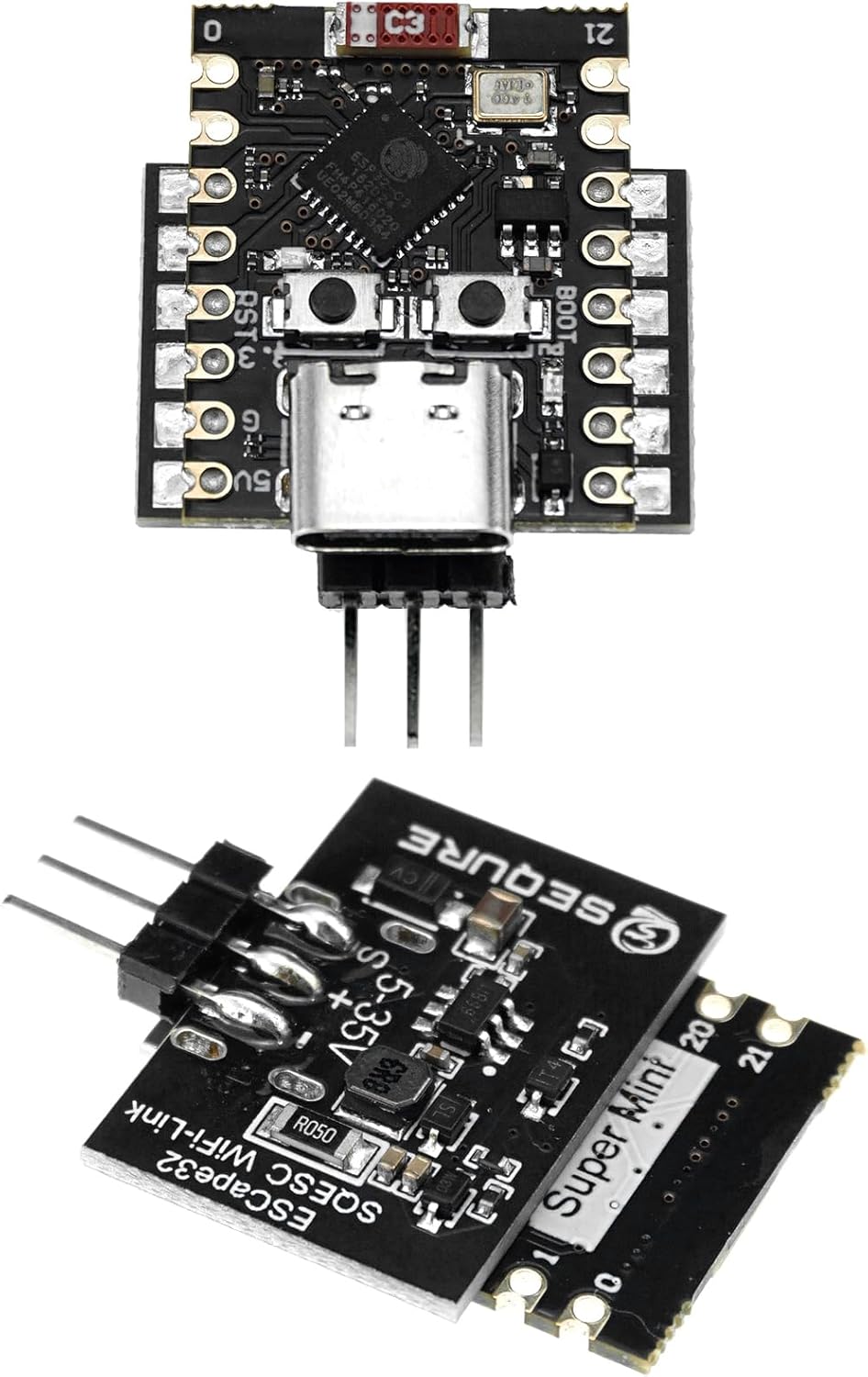
Image 5: The ESCape32 WiFi-Link module, used for wireless parameter configuration and firmware updates.
- Connect the WiFi-Link module to the designated port on the ESC.
- Power on the ESC. The WiFi-Link will create a wireless network.
- Connect your mobile device (smartphone or tablet) to the WiFi-Link's network.
- Open the ESCape32 configuration application on your mobile device.
- You can now adjust various parameters such as motor timing, motor steering, current detection, telemetry settings, and RGB LED colors. Refer to the ESCape32 application's user interface for detailed options.
For detailed instructions on using the ESCape32 firmware and WiFi-Link application, please consult the official ESCape32 documentation or the application's help section.
6. Maintenance
Regular maintenance helps ensure the longevity and optimal performance of your ESC.
- Cleaning: Keep the ESC clean and free from dust, dirt, and moisture. Use a soft brush or compressed air to remove debris. Avoid using liquid cleaners directly on the ESC.
- Inspection: Periodically inspect all wires and connectors for signs of wear, damage, or corrosion. Ensure all solder joints are secure.
- Heat Management: Ensure adequate airflow around the ESC during operation to prevent overheating. The integrated metal heat sink aids in dissipation, but proper ventilation is still important.
- Storage: Store the ESC in a dry, cool environment away from direct sunlight and extreme temperatures.
7. Troubleshooting
If you encounter issues with your SQESC 2670, consider the following troubleshooting steps:
- No Power:
- Check battery connection and charge level.
- Verify all power wires are securely connected and not damaged.
- Ensure the BEC voltage selection (if modified) is correctly soldered.
- Motor Not Responding / Stuttering:
- Perform throttle calibration again.
- Check motor wire connections for looseness or incorrect order.
- Verify signal cable connection to the receiver.
- Check motor timing settings in the ESCape32 application.
- Ensure the motor is compatible with a brushless ESC.
- ESC Overheating:
- Ensure adequate ventilation around the ESC.
- Check for excessive load on the motor or drivetrain.
- Review motor timing settings; aggressive timing can increase heat.
- WiFi-Link Connection Issues:
- Ensure the WiFi-Link module is correctly connected to the ESC.
- Verify the ESC is powered on.
- Check your mobile device's WiFi settings to ensure it's connected to the WiFi-Link's network.
For further assistance, refer to the ESCape32 community forums or contact SEQURE customer support.
8. Safety Information
Always observe the following safety precautions when handling and operating your ESC:
- Battery Safety: Use only compatible Lipo batteries within the specified voltage range (2-6S). Always handle Lipo batteries with care to prevent punctures or damage, which can lead to fire.
- Electrical Safety: Ensure all connections are correct and secure before applying power. Incorrect wiring can cause damage to the ESC, motor, or battery. Avoid short circuits.
- Heat: ESCs can generate significant heat during operation. Avoid touching the ESC immediately after use. Ensure proper ventilation.
- Rotating Parts: Keep hands, hair, and loose clothing away from rotating motor parts when the system is powered on.
- Water and Moisture: This ESC is not waterproof unless explicitly stated. Avoid exposure to water or high humidity.
- Children: This product is not a toy and is recommended for users 14 years and up. Keep out of reach of small children.
9. Customer Support
For technical support, warranty inquiries, or further information, please visit the official SEQURE website or contact their customer service department.
Manufacturer: SEQURE
Website: Visit the SEQURE Store on Amazon