
1. Introduction
This manual provides comprehensive instructions for the installation, operation, and maintenance of your CLEAR VIEW TWOPCWIPERKIT Two-Piece Windshield Defroster System. This system is designed to effectively melt snow and ice from semi-truck windshields, enhancing visibility and safety during cold weather conditions. Please read this manual thoroughly before attempting installation or operation to ensure proper function and longevity of the product.
2. Product Overview
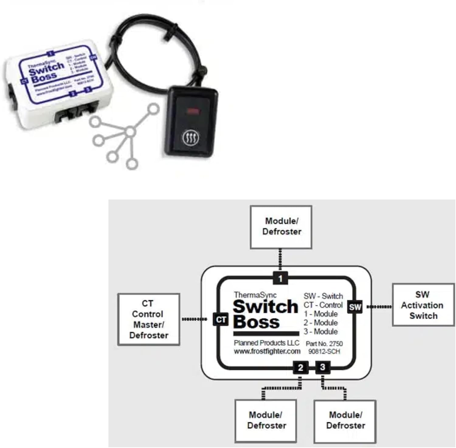
The CLEAR VIEW TWOPCWIPERKIT is a complete two-piece windshield defroster system specifically engineered for semi-truck applications. It includes two defroster elements, two control modules, and a central Switch Boss unit. The system works by applying heat directly to the windshield surface, preventing and clearing ice and snow buildup. The Switch Boss acts as the central control unit, managing the power distribution to the defroster elements.

3. Package Contents
Verify that all components listed below are present in your package:
- Two (2) 1206-2440-L-FWH-HD Defroster Elements
- Two (2) 1204-2027-L-SWH-HD Control Modules
- One (1) 2730 Switch Boss Control Unit

4. Setup and Installation
Installation of the CLEAR VIEW Defroster System requires electrical knowledge and careful adherence to vehicle wiring standards. It is recommended that installation be performed by a qualified technician. Incorrect installation can lead to system malfunction or damage to the vehicle's electrical system.
4.1 Component Placement
The defroster elements are designed for specific placement on the windshield. The two main elements (1206-2440-L-FWH-HD) are typically positioned horizontally across the lower part of the windshield, while the two side elements (1204-2027-L-SWH-HD) are placed vertically along the sides, often near the A-pillars or side mirrors, depending on the semi-truck model.

4.2 Wiring Connections
The Switch Boss unit serves as the central hub for the defroster system. It connects to the vehicle's power source, an activation switch, and the individual defroster modules. Ensure all connections are secure and properly insulated to prevent short circuits and ensure reliable operation.
- SW (Switch): Connects to the activation switch in the vehicle's cabin.
- CT (Control): Connects to the master defroster module.
- Modules 1, 2, 3: Connect to the individual defroster elements via their respective control modules.

5. Operating Instructions
Once installed, operating the CLEAR VIEW Defroster System is straightforward:
- Ensure the vehicle's ignition is on.
- Locate the activation switch installed in your cabin.
- Press the switch to activate the defroster system. The Switch Boss will illuminate or provide an audible click, indicating activation.
- Allow several minutes for the defroster elements to heat up and begin melting ice and snow.
- To deactivate, press the switch again.
For optimal performance, activate the defroster system before significant ice or snow accumulation occurs, or as soon as conditions warrant.
6. Maintenance
The CLEAR VIEW Defroster System is designed for minimal maintenance. However, periodic checks can ensure continued optimal performance:
- Visual Inspection: Regularly inspect the defroster elements on the windshield for any signs of damage, peeling, or wear.
- Wiring Check: Periodically check all wiring connections to the Switch Boss and defroster modules for tightness and corrosion. Ensure all insulation is intact.
- Cleaning: Clean the windshield as usual. Avoid using abrasive cleaners or tools directly on the defroster elements, as this may cause damage.
- Functionality Test: Before the winter season, test the system by activating it and verifying that the elements heat up evenly across the windshield.
7. Troubleshooting
If you encounter issues with your CLEAR VIEW Defroster System, refer to the following troubleshooting guide:
| Problem | Possible Cause | Solution |
|---|---|---|
| Defroster not activating | No power to Switch Boss; Faulty activation switch; Loose wiring connection. | Check vehicle's fuse box; Test activation switch; Inspect all wiring connections for security. |
| Defroster elements not heating | Faulty defroster element; Damaged control module; Wiring issue between Switch Boss and module/element. | Inspect elements for visible damage; Check connections to control modules; Consult a technician for module testing. |
| Uneven heating | Partial damage to element; Poor contact with windshield; Wiring issue. | Inspect element for damage; Ensure proper adhesion to windshield; Check wiring for intermittent connections. |
| Switch Boss indicator light off | No power; Internal fault. | Verify power supply to Switch Boss; If power is present, the unit may require professional inspection or replacement. |
8. Specifications
- Model: TWOPCWIPERKIT
- Item Weight: 3.03 pounds
- Package Dimensions: 11.46 x 9.13 x 6.81 inches
- Manufacturer Part Number: TWOPCWIPERKIT
- ASIN: B0DGRGJR7L
9. Warranty and Support
For information regarding product warranty, returns, or technical support, please refer to the documentation provided with your purchase or contact CLEAR VIEW directly through their official channels. Keep your proof of purchase for any warranty claims.
Manufacturer: CLEAR VIEW