1. Introduction
Thank you for choosing the Acegeek Iliad Mini Mid-Tower Gaming PC Case. This manual provides essential information for the proper installation, operation, and maintenance of your new PC case. Please read this guide thoroughly before beginning the assembly process to ensure optimal performance and longevity of your components.
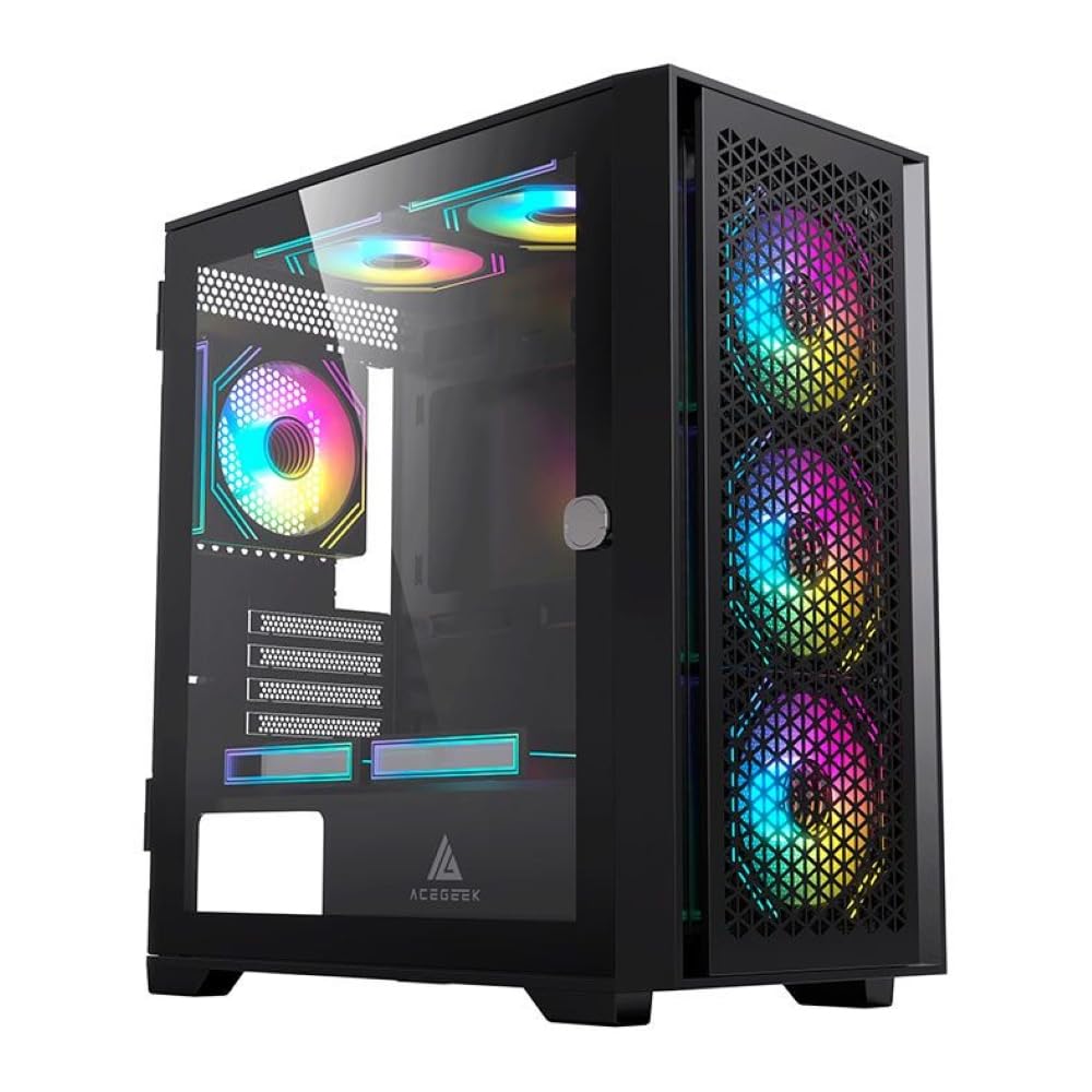
Figure 1: Acegeek Iliad Mini Mid-Tower Gaming PC Case. This image shows the exterior of the black PC case, highlighting the mesh front panel with three illuminated RGB fans and the tempered glass side panel revealing internal components.
2. Safety Information
Please observe the following safety precautions during installation and operation:
- Always disconnect the power supply from the wall outlet before installing or removing any components to prevent electric shock.
- Handle internal components with care to avoid damage from electrostatic discharge (ESD). Consider using an anti-static wrist strap.
- Keep the case away from sources of heat, direct sunlight, and excessive moisture.
- Ensure proper ventilation to prevent overheating. Do not block air vents.
- The tempered glass panel is fragile. Handle with extreme care to prevent breakage.
- Keep small parts and tools out of reach of children.
3. Product Features
The Acegeek Iliad Mini is designed for both aesthetics and performance, offering a modern solution for your gaming PC build.
- Mid-Tower Form Factor: Compact yet spacious design for various component configurations.
- Tempered Glass Side Panel: Provides a clear view of your internal hardware and RGB lighting.
- Optimized Airflow: Mesh front panel and multiple fan mounting options ensure efficient cooling.
- Versatile Storage Options: Supports both HDDs and SSDs for flexible storage solutions.
- Cable Management: Dedicated space behind the motherboard tray for tidy cable routing.
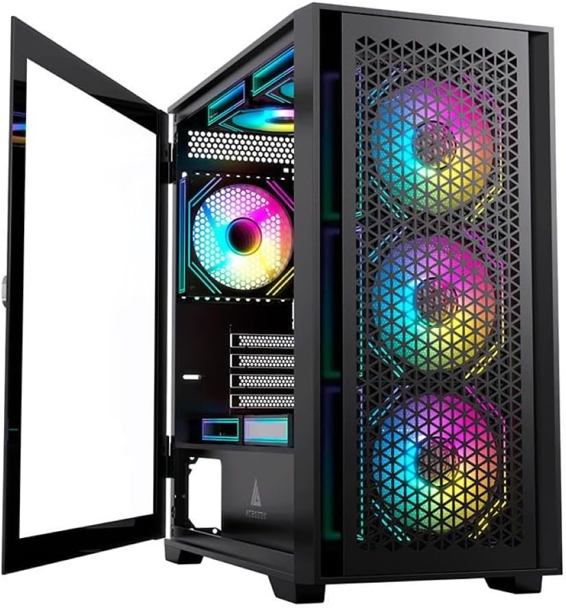
Figure 2: Open Tempered Glass Side Panel. This image displays the PC case with its hinged tempered glass side panel swung open, providing full access to the interior for component installation and maintenance.
4. Setup Guide
Follow these steps to assemble your PC components within the Acegeek Iliad Mini case.
4.1 Preparing the Case
- Place the case on a flat, stable surface.
- Carefully open the tempered glass side panel. It may be hinged or secured with thumbscrews. Refer to Figure 2 for an example of the open panel.
- Remove any packaging materials or accessories from inside the case.
4.2 Motherboard Installation
- Install the I/O shield into the rear opening of the case.
- Align your Micro-ATX or ITX motherboard with the standoffs inside the case.
- Secure the motherboard using the provided screws.
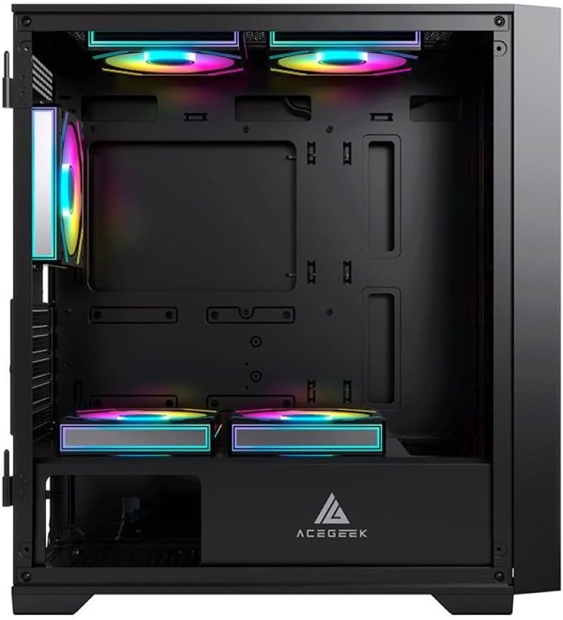
Figure 3: Case Interior. This image provides a clear view of the internal structure of the PC case, including the motherboard mounting area, drive bays, and fan mounting points, without the side panel.
4.3 Storage Device Installation
- 2.5" SSDs: Locate the dedicated SSD mounting points, typically behind the motherboard tray or on the PSU shroud. Secure SSDs with screws.
- 3.5" HDDs: Install HDDs into the drive cages, usually located beneath the PSU shroud. Slide the HDD into the bay and secure it if necessary.
4.4 Graphics Card (VGA) Installation
- Remove the necessary expansion slot covers from the rear of the case.
- Insert your graphics card into the appropriate PCIe slot on the motherboard.
- Secure the graphics card with screws. The case supports VGA cards up to 360 mm in length.
4.5 Cooling System Installation (Fans & Radiators)
The Acegeek Iliad Mini supports various cooling configurations. Note that fans are not included with the case.
- Front: Up to 3 x 120 mm or 2 x 140 mm fans. Radiator support up to 360 mm.
- Top: Up to 2 x 120 mm or 2 x 140 mm fans. Radiator support up to 240 mm / 280 mm.
- Rear: 1 x 120 mm fan.
- PSU Cover: Up to 2 x 120 mm fans.
- CPU Cooler: Maximum height of 165 mm.
Install fans and radiators according to your cooling needs, ensuring proper airflow direction.
4.6 Power Supply Unit (PSU) Installation
- Slide the PSU into its designated compartment at the bottom rear of the case.
- Secure the PSU with screws from the rear of the case. The case supports PSUs up to 190 mm in length.
4.7 Cable Management
Utilize the 20 mm cable management space behind the motherboard tray to route and secure cables. This improves airflow and aesthetics.
- Connect all necessary power cables from the PSU to your components (motherboard, GPU, drives).
- Connect front panel cables (USB, audio, power/reset switches, LEDs) to the appropriate headers on your motherboard.
- Bundle and secure excess cables using zip ties or Velcro straps.
5. Operating Instructions
Once all components are installed and cables are connected:
- Close and secure the tempered glass side panel.
- Connect your monitor, keyboard, mouse, and other peripherals to the rear I/O ports of your motherboard.
- Connect the power cable to the PSU and then to a wall outlet.
- Flip the power switch on the PSU to the 'ON' position.
- Press the power button on the front panel of the case to start your computer.
6. Maintenance
Regular maintenance helps ensure optimal performance and extends the lifespan of your PC components.
- Dust Cleaning: Periodically clean dust from the case interior, fans, and filters using compressed air or a soft brush. Ensure the PC is powered off and unplugged before cleaning.
- Tempered Glass: Clean the tempered glass panel with a soft, lint-free cloth and a mild glass cleaner. Avoid abrasive materials.
- Airflow: Ensure all fan vents are clear of obstructions to maintain good airflow.
7. Troubleshooting
If you encounter issues during or after assembly, consider the following common troubleshooting steps:
- No Power: Ensure the PSU is switched on, all power cables are securely connected to the motherboard and components, and the front panel power switch cable is correctly connected to the motherboard header.
- No Display: Verify that the graphics card is properly seated in its PCIe slot and that the monitor cable is connected to the graphics card (not the motherboard's integrated graphics ports, unless you are using integrated graphics).
- Fans Not Spinning: Check that all fan power cables are correctly connected to the motherboard or fan controller.
- Overheating: Ensure all fans are installed correctly and spinning in the right direction for optimal airflow. Check for dust buildup.
8. Specifications
Detailed technical specifications for the Acegeek Iliad Mini PC Case:
| Feature | Specification |
|---|---|
| Model Name | Iliad Mini (AG-ILIAD-MINI-BK) |
| Case Type | Mid-Tower |
| Material | ABS, Mesh, Tempered Glass |
| Motherboard Support | Micro-ATX, ITX |
| Drive Bays | 2 x 3.5" HDD, 2 x 2.5" SSD |
| Expansion Slots | 5 |
| Max CPU Cooler Height | 165 mm |
| Max VGA Length | 360 mm |
| Max PSU Length | 190 mm |
| Cable Management Space | 20 mm |
| Dimensions (L x W x H) | 410 x 210 x 450 mm |
| Fan Support (Front) | 3 x 120 mm or 2 x 140 mm |
| Fan Support (Top) | 2 x 120 mm or 2 x 140 mm |
| Fan Support (Rear) | 1 x 120 mm |
| Fan Support (PSU Cover) | 2 x 120 mm |
| Radiator Support (Front) | Up to 360 mm |
| Radiator Support (Top) | Up to 240 mm / 280 mm |
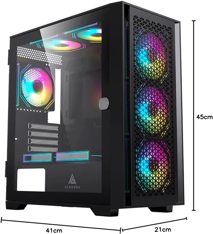
Figure 4: Case Dimensions. This diagram illustrates the length (41 cm), width (21 cm), and height (45 cm) of the Acegeek Iliad Mini PC case.
9. Warranty and Support
For warranty information and technical support, please refer to the documentation provided with your purchase or visit the official Acegeek website. Keep your proof of purchase for warranty claims.
If you require further assistance, please contact Acegeek customer support.