1. Introduction
The FORYON SF-2100C CNC Lathe Controller is a systematic solution designed for precise control of various CNC machines. It integrates a human-computer interface for intuitive operation and code analysis, while an FPGA provides the underlying algorithms and generates control pulses, ensuring reliable performance and ease of use. The internal operating system is designed for efficiency and stability.
This controller is versatile and can be applied to a wide range of CNC machinery, including lathes, CNC routers, pick-and-place machines, and milling machines. Its design prioritizes convenient operation and high precision.
The user-friendly interface allows operators to quickly become proficient. Commands can be input via a touch screen or keyboard, enabling intuitive setting of processing parameters and programs. Advanced versions may support graphical programming, simplifying the programming process significantly.
The SF-2100C controller achieves high-precision machining through advanced digital control technology. It precisely manages the position and speed of the machining process, ensuring accuracy and consistency in dimensions. Furthermore, features like error compensation enhance overall machining precision.
2. Setup and Installation
Proper installation is crucial for the optimal performance and longevity of your SF-2100C controller. Follow these steps carefully:
2.1 Physical Placement
Mount the controller securely in a location that is stable, free from excessive vibration, dust, and moisture. Ensure adequate ventilation around the unit to prevent overheating.

Figure 2.1: Front panel of the SF-2100C controller, featuring the display and integrated keypad for user interaction.
2.2 Electrical Connections
Refer to the rear panel diagram for correct wiring. Ensure all connections are secure before powering on the device.
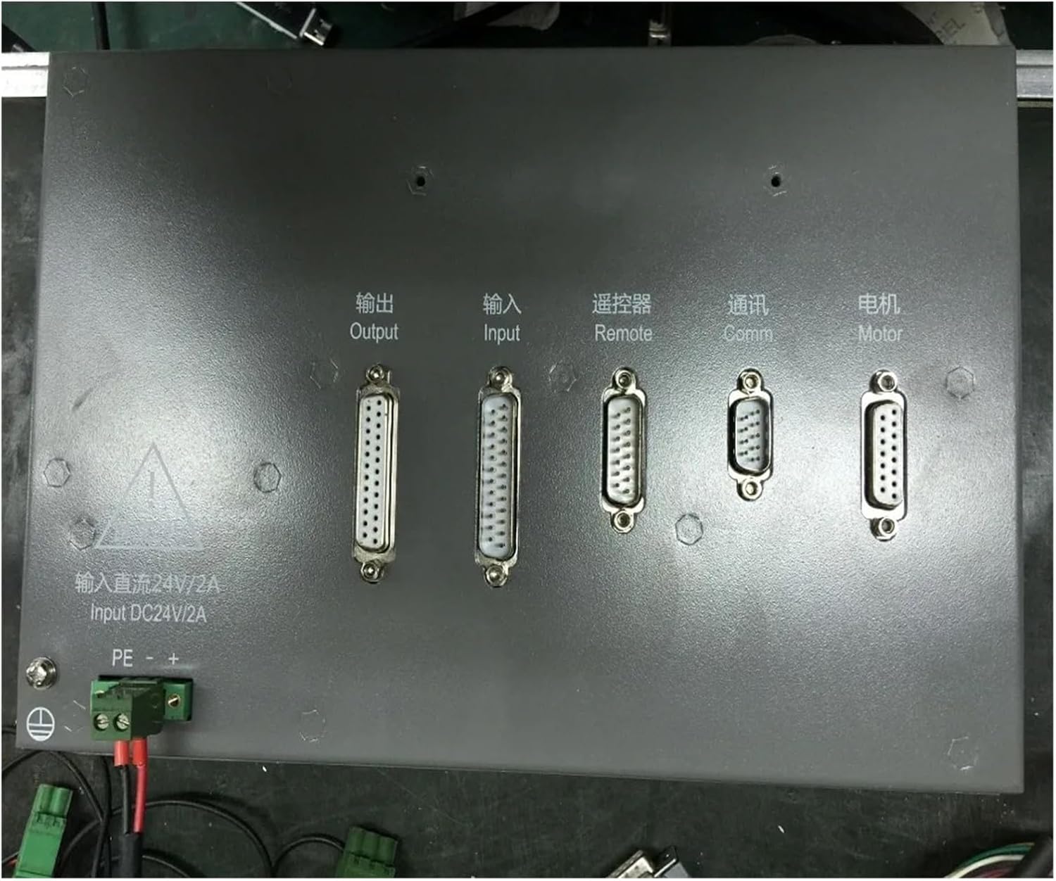
Figure 2.2: Rear panel connections of the SF-2100C controller. From left to right: Output, Input, Remote, Communication (Comm), and Motor ports. Below these are the DC24V/2A power input terminals.
- Power Input: Connect a stable DC 24V/2A power supply to the designated terminals labeled "Input DC24V/2A". Ensure correct polarity (+ and -).
- Output: Connect to the output devices of your CNC machine (e.g., relays, solenoids) using the specified multi-pin connector.
- Input: Connect to input signals from your CNC machine (e.g., limit switches, emergency stop buttons) using the specified multi-pin connector.
- Remote: Connect to a remote control pendant or device, if applicable, via this port.
- Comm (Communication): Use this port for data communication with other systems or for software updates.
- Motor: Connect to the motor drive systems of your CNC machine (e.g., stepper or servo motor drivers) via this port.
- Ground (PE): Ensure the controller is properly grounded to prevent electrical hazards and interference.
Always power off the controller and connected machinery before making or changing any electrical connections.
3. Operating Instructions
The SF-2100C controller is designed for intuitive operation. Familiarize yourself with the control panel and display before beginning any operations.
3.1 Control Panel Overview
The front panel (Figure 2.1) features a large display screen and a comprehensive keypad. The keypad includes:
- Numeric Keypad: For entering numerical values and coordinates.
- Navigation Keys: Arrows (Up, Down, Left, Right) for menu navigation and cursor movement.
- Function Keys (F1-F7): Context-sensitive keys whose functions are typically displayed on the bottom of the screen.
- Special Function Keys: Such as ESC (Escape), DEL (Delete), HOME, END, PgUp, PgDn, and specific operational keys like IGNITING, CUTORY, PREHEA, CLOSE.
- Start/Stop Buttons: Typically green for start/run and red for stop/emergency stop.
3.2 Display Interface
The display provides real-time information about the machine status, program execution, and various parameters. An example of the display interface is shown below:

Figure 3.1: Example of the SF-2100C display interface. It shows current speed, program number, hole sequence number, cutting parameters, coordinate values (X, Y), and soft key functions at the bottom.
Key information typically displayed includes:
- Current Speed: Real-time feed rate.
- Program/File Information: Current program name or number, line number.
- Coordinate Display: X, Y, (and potentially Z) axis positions.
- Cutting Parameters: Such as cutting mode (e.g., plasma, flame), cutting speed, preheat time, scaling factor.
- Status Indicators: For various machine functions (e.g., torch lift, torch down, arc voltage detection, cutting position).
- Soft Key Functions: The functions of the F1-F7 keys change depending on the current screen or mode. These are usually labeled at the bottom of the display.
3.3 Basic Operation Workflow
- Power On: Ensure all connections are secure, then apply power to the controller.
- Initialization: The system will perform a self-check. Wait for the main interface to load.
- Load Program: Navigate through the menu to load your desired G-code or cutting program.
- Set Parameters: Adjust cutting parameters (e.g., speed, height, preheat) as required for your material and operation.
- Home Machine: If necessary, home the machine axes to establish reference points.
- Start Operation: Press the green start button to begin the cutting or machining process.
- Monitor Progress: Observe the display for real-time status and make adjustments if needed.
- Stop Operation: Use the red stop button or emergency stop in case of issues or at the end of the process.
For detailed programming and advanced features, refer to the comprehensive software manual provided with the controller.
4. Maintenance
Regular maintenance ensures the longevity and reliable performance of your SF-2100C controller.
- Cleaning: Periodically clean the exterior of the controller, especially the display screen and keypad, with a soft, dry, lint-free cloth. Avoid using abrasive cleaners or solvents.
- Dust Control: Ensure the operating environment is as dust-free as possible. Dust accumulation can affect internal components and cooling.
- Connection Check: Regularly inspect all cable connections (power, input, output, communication, motor) to ensure they are secure and free from damage. Loose connections can lead to intermittent operation or errors.
- Environmental Conditions: Operate the controller within its specified temperature and humidity ranges. Avoid extreme temperatures or high humidity, which can damage electronic components.
- Software Updates: Check with the manufacturer or authorized service provider for any available firmware or software updates that may improve performance or add features.
Always power off and disconnect the controller from the power source before performing any cleaning or maintenance.
5. Troubleshooting
This section provides basic troubleshooting steps for common issues. For more complex problems, contact technical support.
| Problem | Possible Cause | Solution |
|---|---|---|
| Controller does not power on. | No power supply; loose power connection; faulty power supply. | Check power cable connection. Verify power outlet. Test power supply voltage (should be DC 24V). |
| Display screen is blank or distorted. | Loose internal display cable; software error; hardware malfunction. | Restart the controller. If problem persists, contact technical support. |
| Machine not responding to commands. | Loose motor/output connections; incorrect program loaded; emergency stop engaged. | Check all motor and output cable connections. Verify the loaded program. Ensure emergency stop is disengaged. |
| Inaccurate cutting or movement. | Incorrect calibration; mechanical issues with machine; program error. | Review machine calibration settings. Inspect mechanical components of the CNC machine. Verify G-code program for errors. |
If you encounter issues not listed here or if the suggested solutions do not resolve the problem, please contact FORYON technical support.
6. Specifications
Key technical specifications for the SF-2100C CNC Lathe Controller:
| Attribute | Detail |
|---|---|
| Model Number | SF-2100C (FORYON) |
| Brand | FORYON |
| Package Dimensions | 1.18 x 0.79 x 0.39 inches |
| Item Weight | 7.35 pounds |
| Manufacturer | FORYON |
| Assembly Required | No |
| Number of Pieces | 1 |
| Power Input | DC 24V/2A (as indicated on rear panel) |
7. Warranty and Support
FORYON products are designed for reliability and performance. For information regarding warranty coverage, please refer to the warranty card included with your product or contact the seller directly. Warranty terms may vary based on region and purchase date.
For technical assistance, troubleshooting beyond this manual, or inquiries about spare parts, please contact FORYON customer support or your authorized dealer. When contacting support, please have your product model number (SF-2100C) and purchase details ready.
Contact Information: Please refer to the contact details provided on the product packaging or the official FORYON website for the most up-to-date support information.