1. Introduction
This manual provides essential information for the safe and efficient installation, operation, and maintenance of your DMBGRXJF PPR Brass Motorized Ball Valve, model PPR50 24VDC_CR04. Please read these instructions thoroughly before use and retain them for future reference.
2. Safety Information
Observe all local codes and regulations during installation and operation. Failure to follow these instructions may result in property damage, personal injury, or death.
- Ensure power is disconnected before any installation, maintenance, or troubleshooting.
- Verify the voltage and current ratings of the valve match your power supply.
- Do not operate the valve beyond its specified pressure and temperature limits.
- Installation should be performed by qualified personnel.
- Wear appropriate personal protective equipment (PPE) during installation and maintenance.
3. Product Overview
The DMBGRXJF PPR Brass Motorized Ball Valve is designed for controlling the flow of cold/hot water and 60% Ethylene Glycol in various applications. It features a brass body, a motorized actuator, and PPR connections for reliable performance.

Figure 3.1: Side view of the DMBGRXJF PPR Brass Motorized Ball Valve, showing the red actuator and brass valve body.

Figure 3.2: Disassembled view of the valve, showing the main valve body, actuator, and connection fittings.
4. Specifications
| Model | PPR50 24VDC_CR04 |
| Medium | Cold/hot water, 60% Ethylene Glycol |
| Material | Brass (Valve Body) |
| Power Supply | 24VDC |
| Structure Forms | Two Ways |
| Operation Mode | Three Wire Two Ways Control / Three-wire One Control mode / 2-wire (power-off reset mode) |
| Power Consumption | 6W (Only when the valve opens and closes) |
| Running Time | 5-15 Seconds |
| Nominal Pressure | 1.6MPa |
| Medium Temperature | 2°C ~ 95°C |
| Maximum Differential Pressure | 1.0MPa |
| Connection Mode | G Internal Thread |
| NC or NO | Normally Closed |
| Actuator Mode | With Manual And Instruction |
| Port Size | PPR50 |
5. Setup and Installation
Proper installation is crucial for the valve's performance and longevity. Refer to the following steps:
- Preparation: Ensure the power supply is disconnected. Close main water supply valves to prevent leaks.
- Inspect Components: Verify all parts are present and undamaged.
- Mounting: Install the valve in the desired position, ensuring the flow direction matches the system requirements. The valve can be installed in any orientation, but vertical installation with the actuator above the valve body is recommended to prevent moisture ingress into the actuator.
- Pipe Connection: Connect the PPR pipes to the valve's G internal threads. Use appropriate sealing tape or compound to ensure a watertight connection. Avoid overtightening.
- Electrical Wiring:
- Three-Wire Two-Control Mode (CR04): Connect the power supply (24VDC) to the designated terminals. Typically, one wire is common, one for opening, and one for closing. Refer to the wiring diagram provided with your specific model for exact connections.
- Two-Wire (Power-off Reset Mode): Connect the two wires to the power supply. The valve will open/close when power is applied and return to its default (normally closed) position when power is removed.
Caution: Incorrect wiring can damage the valve or cause electrical hazards. Consult a qualified electrician if unsure.
- Testing: Once installed and wired, slowly restore the water supply and check for leaks. Then, restore power and test the valve's operation (opening and closing) to ensure it functions correctly.
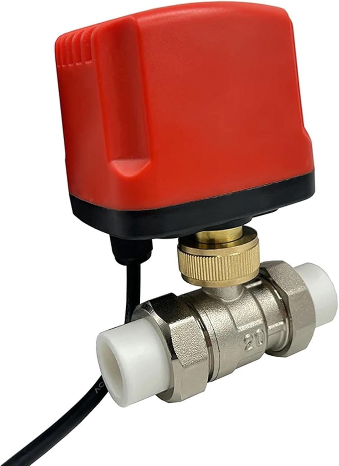
Figure 5.1: Assembled valve with electrical wiring connected to the actuator.
6. Operating Instructions
The motorized ball valve operates based on the electrical signals received by its actuator. The specific operation depends on the wiring mode (CR04 for 3-wire 2-control, or 2-wire power-off reset).
- Automatic Operation: In most installations, the valve is controlled by a thermostat, timer, or building management system. The actuator will automatically open or close the valve based on the control signal.
- Manual Override: Some models may include a manual override lever or knob on the actuator. If present, this allows for manual positioning of the valve in case of power failure or for maintenance. Refer to the actuator's specific markings for manual operation.
- Indicator: The actuator typically has a visual indicator to show the current position of the valve (open or closed).
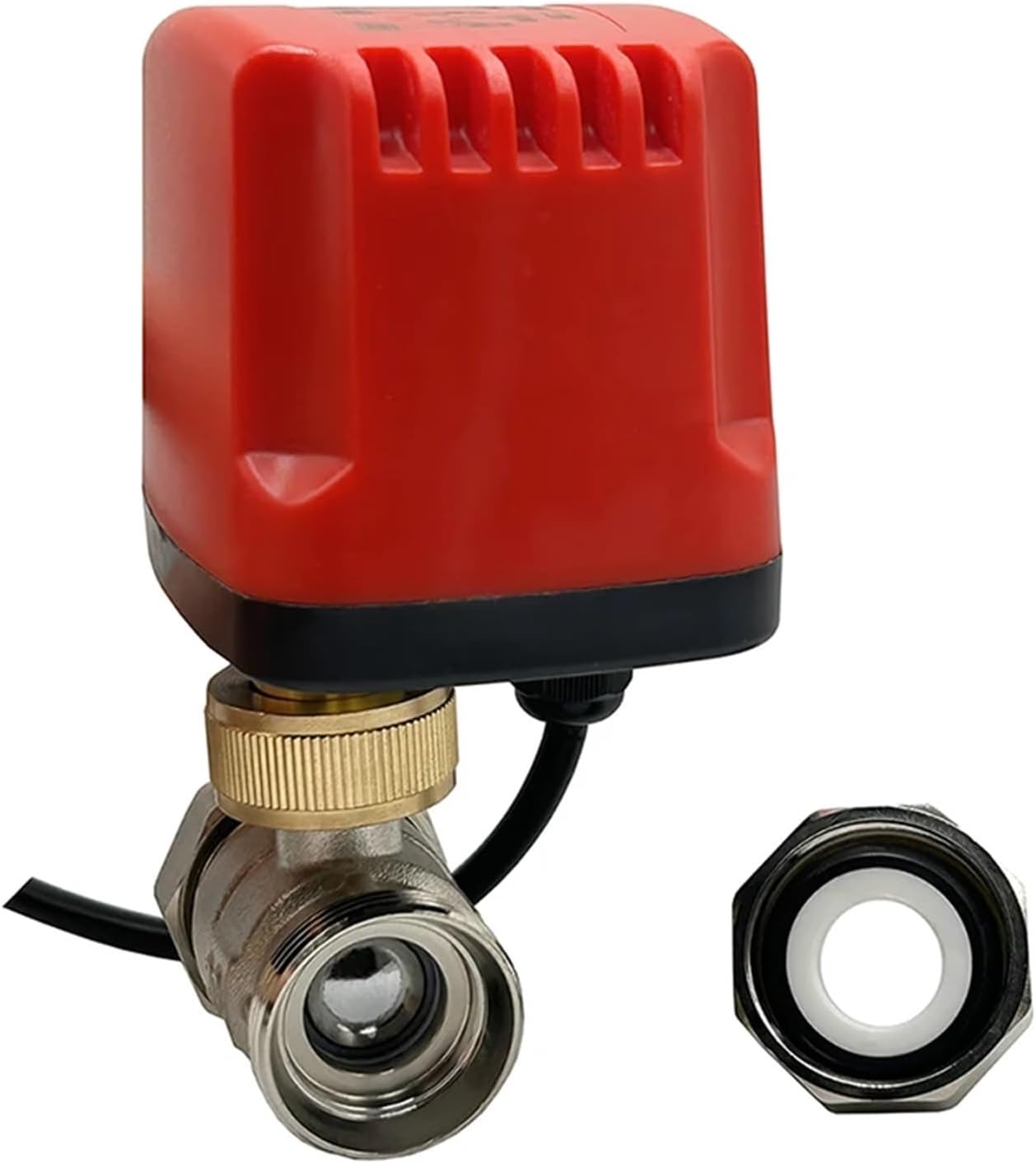
Figure 6.1: Close-up view of the valve's internal ball mechanism, indicating flow path.
7. Maintenance
The DMBGRXJF PPR Brass Motorized Ball Valve is designed for low maintenance. However, periodic checks can ensure optimal performance.
- Visual Inspection: Periodically inspect the valve and actuator for any signs of leaks, corrosion, or physical damage.
- Electrical Connections: Ensure all electrical connections are secure and free from corrosion.
- Cleaning: Clean the exterior of the actuator and valve body with a damp cloth. Do not use abrasive cleaners or solvents.
- Functionality Check: Occasionally cycle the valve (open and close) to ensure smooth operation.
- Winterization: If the system is subject to freezing temperatures, ensure proper winterization procedures are followed to prevent damage to the valve and piping.
8. Troubleshooting
Refer to the table below for common issues and their potential solutions.
| Problem | Possible Cause | Solution |
|---|---|---|
| Valve does not open/close | No power to actuator; Incorrect wiring; Actuator failure; Obstruction in valve. | Check power supply and connections; Verify wiring against diagram; Replace actuator; Inspect valve for debris (with power off and system depressurized). |
| Valve leaks | Loose connections; Damaged seals; Incorrect installation. | Tighten pipe connections (do not overtighten); Replace valve if seals are damaged; Reinstall correctly. |
| Valve operates slowly | Low voltage; Mechanical resistance. | Verify power supply voltage; Check for any external obstructions or internal debris. |
If troubleshooting steps do not resolve the issue, contact qualified service personnel.
9. Warranty and Support
For warranty information and technical support, please refer to the documentation provided at the time of purchase or contact DMBGRXJF customer service. Keep your purchase receipt as proof of purchase.
Manufacturer: DMBGRXJF
ASIN: B0DGD4CQS4
Date First Available: September 7, 2024