1. Introduction
This manual provides essential information for the safe and effective use of the BAISULI FX2N-14MT PLC Programmable Controller Board. This industrial control device is designed for various automation tasks, offering reliable performance in diverse environments. Please read this manual thoroughly before installation, operation, or maintenance.
2. Safety Information
Always observe the following safety precautions to prevent injury or damage to the equipment:
- Ensure power is disconnected before performing any wiring or maintenance.
- Only qualified personnel should install, operate, and maintain this device.
- Verify all wiring connections are correct and secure before applying power.
- Do not expose the device to moisture, extreme temperatures, or corrosive environments.
- Use appropriate personal protective equipment (PPE) when working with electrical systems.
3. Product Overview
The BAISULI FX2N-14MT is a compact and robust Programmable Logic Controller board suitable for various industrial automation applications. It features relay output and 2-channel analog input (0-10V).
3.1 Features
- Relay output module with stable structure and excellent performance.
- Designed to operate without fear of various harsh electromagnetic interference working environments.
- Suitable for industrial control equipment in production machinery, industrial assembly lines, and various machine tools.
- Flexibly used in industrial automatic control occasions such as metallurgy, chemical industry, plastics, textile, food, packaging, printing, building materials, woodworking, central air conditioning, and environmental protection equipment.
3.2 Components
The PLC board includes various terminals for power, inputs, and outputs, along with communication ports. A typical board layout is shown below:
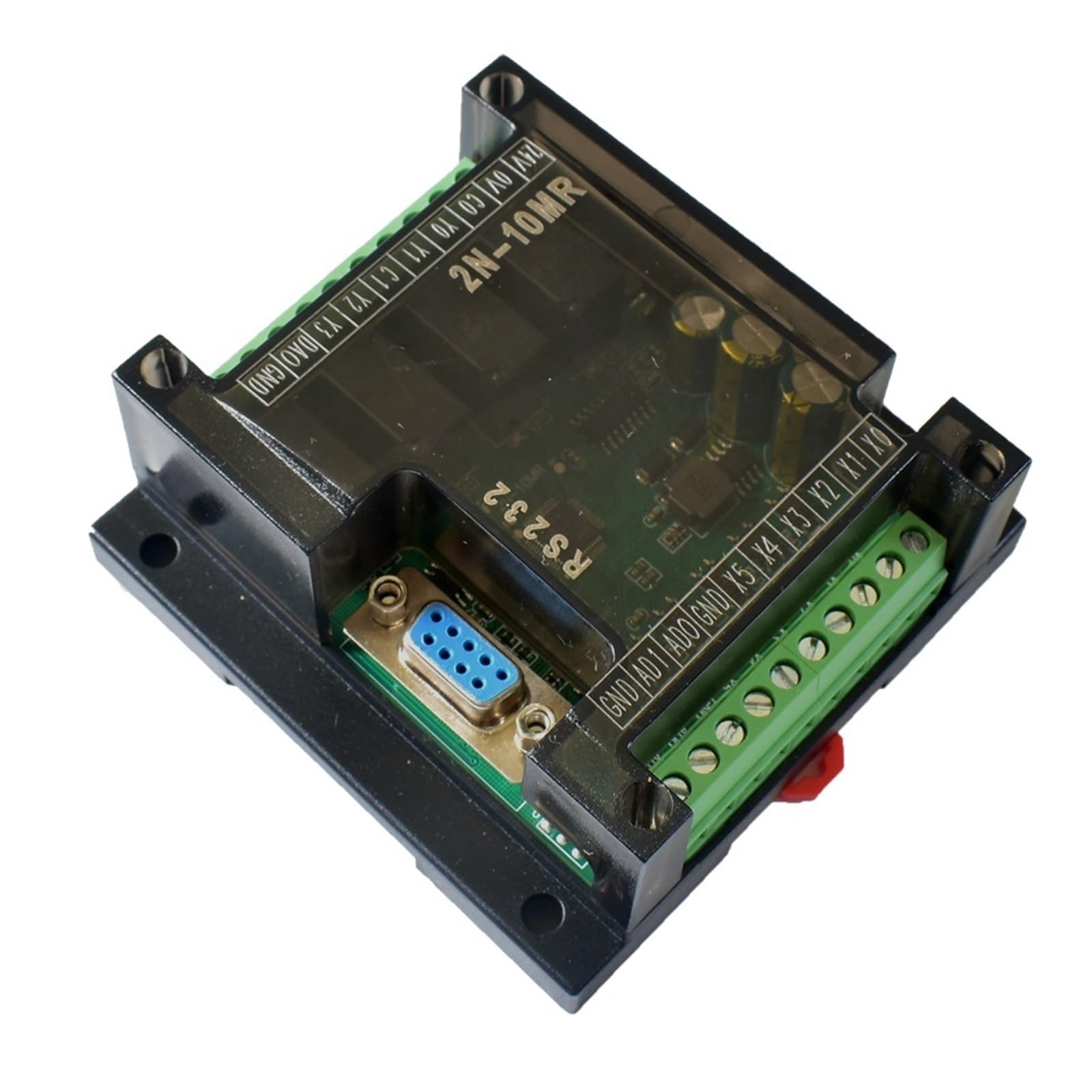
Image 3.1: BAISULI FX2N-14MT PLC Programmable Controller Board. This image displays the overall layout of the controller board, including its various connection terminals and the main circuit board.
4. Setup
4.1 Mounting
Mount the PLC board securely within an appropriate control panel or enclosure, ensuring adequate ventilation and protection from environmental factors. Use the mounting holes provided on the board.
4.2 Wiring
Follow these general guidelines for wiring the PLC:
- Power Supply: Connect the appropriate DC power supply (e.g., 24V DC) to the designated power terminals (e.g., 24V, 0V). Ensure correct polarity.
- Digital Inputs: Connect sensors, switches, and other digital input devices to the input terminals (e.g., X0-Xn). Refer to the specific terminal markings on your board.
- Digital Outputs: Connect actuators, relays, and other digital output devices to the output terminals (e.g., Y0-Yn). Ensure the load current does not exceed the relay contact ratings.
- Analog Inputs: For the 2-channel 0-10V analog inputs, connect analog sensors or signal generators to the designated analog input terminals (e.g., AD0, AD1). Ensure the input voltage range matches the PLC's specifications.
- Communication: Connect the PLC to a programming device (e.g., PC) via the RS232 serial port for programming and monitoring.
5. Operating Instructions
5.1 Software Installation
Install the appropriate PLC programming software (e.g., GX Developer or compatible software) on your computer. Refer to the software's documentation for installation steps.
5.2 Programming
- Connect the PLC to your computer using a compatible RS232 programming cable.
- Launch the programming software and establish communication with the PLC.
- Create a new project and write your ladder logic program or other supported programming language.
- Download the program to the PLC.
- Monitor the PLC's status and I/O values through the software to verify correct operation.
5.3 Analog Input Configuration
For the 0-10V analog inputs, ensure your program correctly scales and processes the analog values. The raw digital values read by the PLC will correspond to the input voltage, and scaling is typically required to convert these into meaningful engineering units.
6. Maintenance
Regular maintenance helps ensure the longevity and reliable operation of your PLC board:
- Cleaning: Periodically clean the board and enclosure to remove dust and debris. Use a soft, dry cloth or compressed air. Do not use liquid cleaners.
- Inspection: Regularly inspect wiring connections for looseness or damage. Check for any signs of overheating or component degradation.
- Environmental Control: Ensure the operating environment remains within the specified temperature and humidity ranges.
7. Troubleshooting
| Problem | Possible Cause | Solution |
|---|---|---|
| PLC does not power on | No power supply; incorrect wiring; faulty power supply | Check power connections and voltage; verify power supply functionality. |
| Inputs not responding | Sensor faulty; incorrect wiring; program error | Check sensor operation; verify input wiring; debug PLC program. |
| Outputs not activating | Actuator faulty; incorrect wiring; program error; overloaded output | Check actuator; verify output wiring; debug PLC program; ensure load is within specifications. |
| Communication error with PC | Incorrect cable; wrong COM port; software settings; driver issues | Use correct RS232 cable; select correct COM port in software; check baud rate and parity settings; install/update drivers. |
| Analog input reading incorrect | Sensor faulty; incorrect wiring; scaling error in program | Verify analog sensor output; check wiring to AD terminals; review analog scaling logic in PLC program. |
8. Specifications
| Feature | Detail |
|---|---|
| Model | FX2N-14MT |
| Analog Inputs | 2-channel, 0-10V |
| Output Type | Relay |
| Package Dimensions | 1.18 x 0.79 x 0.39 inches |
| Item Weight | 14.1 ounces |
| Manufacturer | BAISULI |
| Number of Pieces | 1 |
9. Warranty and Support
This product comes with a standard manufacturer's warranty. For specific warranty terms, technical support, or service inquiries, please contact BAISULI directly through their official channels or the retailer from whom the product was purchased. Keep your purchase receipt as proof of purchase.