1. Introduction
This manual provides detailed instructions for the installation, operation, and maintenance of your VBESTLIFE Z490 Gaming Plus Motherboard. Please read this guide thoroughly before proceeding with installation to ensure proper setup and to maximize the performance and longevity of your system. This motherboard is designed to support 10th and 11th generation Intel Core, Pentium Gold, and Celeron processors with an LGA 1200 socket.
2. Safety Information
- Always disconnect the power cord from the wall outlet before touching any components inside the computer case.
- Use an anti-static wrist strap or frequently touch a grounded metal object (like the computer case) to discharge static electricity before handling components.
- Handle components by their edges to avoid touching sensitive circuits.
- Keep the motherboard away from moisture and extreme temperatures.
- Ensure proper ventilation within your computer case to prevent overheating.
3. Package Contents
Please check the package contents carefully. If any item is missing or damaged, contact your retailer.
- VBESTLIFE Z490 Gaming Plus Motherboard
- User Manual (this document)
- SATA Data Cables (quantity may vary)
- I/O Shield (if not pre-installed on the motherboard)
4. Motherboard Layout
Familiarize yourself with the various components and connectors on your motherboard. This section highlights key areas for installation.

Image 4.1: General overview of the Z490 Gaming Plus Motherboard, showing the CPU socket, RAM slots, PCIe slots, and I/O panel.
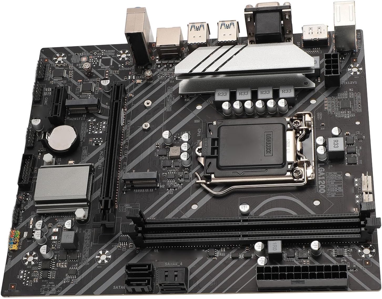
Image 4.2: A detailed view of the LGA 1200 CPU socket and the adjacent I/O ports, including USB and display outputs.

Image 4.3: A closer look at the LGA 1200 CPU socket, showing the retention arm and pin alignment area.

Image 4.4: A detailed view of the M.2 slot and PCIe x1 slots, important for storage and expansion cards.
5. Setup and Installation
Follow these steps carefully to install your components onto the motherboard.
5.1 CPU Installation
The Z490 Gaming Plus motherboard supports LGA 1200 processors.
- Locate the LGA 1200 CPU socket on the motherboard.
- Gently push down the small lever on the side of the socket and pull it away from the socket to open the CPU retention frame.
- Carefully align the triangular mark on your CPU with the corresponding mark on the socket. Ensure the notches on the CPU align with the keys in the socket.
- Place the CPU straight down into the socket without applying force. Do not drop the CPU.
- Close the retention frame and push the lever back into its locked position.

Image 5.1: The motherboard highlighting the CPU socket area, indicating support for LGA 1200 processors.
5.2 RAM Installation
This motherboard features 2 DDR4 DIMM slots, supporting up to 64GB (32GB x 2) of memory.
- Locate the DDR4 DIMM slots on the motherboard.
- Open the retention clips on both ends of the DIMM slot.
- Align the notch on the DDR4 memory module with the key in the DIMM slot.
- Insert the memory module firmly into the slot until the retention clips snap into place on both sides.

Image 5.2: The motherboard displaying various interfaces, including the DDR4 RAM slots, which support dual-channel memory.
5.3 Storage Installation
The motherboard includes M.2 and SATA 3.0 interfaces for storage devices.
M.2 SSD Installation
The M.2 interface supports 32GB/s data transfer speed and is compatible with NGFF and NVME protocols.
- Locate the M.2 slot(s) on the motherboard.
- Remove the M.2 standoff screw from the motherboard.
- Insert the M.2 SSD into the slot at a 30-degree angle.
- Gently push the M.2 SSD down and secure it with the standoff screw.

Image 5.3: The motherboard with the M.2 interface clearly visible, indicating its high-speed data transfer capabilities.
SATA Device Installation
The motherboard provides 4 Serial ATA 3.0 ports for traditional hard drives and SSDs.
- Connect one end of the SATA data cable to a SATA 3.0 port on the motherboard.
- Connect the other end of the SATA data cable to your SATA hard drive or SSD.
- Connect a SATA power cable from your power supply unit (PSU) to the SATA storage device.

Image 5.4: The motherboard highlighting the Serial ATA 3.0 ports, offering high-speed connectivity for storage devices.
5.4 Graphics Card Installation
The motherboard features a PCIe X16 Gen 3.0 graphics slot.
- Locate the PCIe X16 slot on the motherboard.
- Open the retention clip at the end of the slot.
- Align your graphics card with the slot and press down firmly until it is fully seated and the retention clip locks into place.
- Secure the graphics card to your computer case with a screw.
- Connect any necessary PCIe power cables from your PSU to the graphics card.
5.5 Power Supply Connections
Proper power connections are crucial for system stability.
- Connect the 24-PIN ATXPWR connector from your power supply to the main power header on the motherboard. Ensure it clicks into place.
- Connect the 8-PIN ATX12V connector from your power supply to the CPU power header, usually located near the CPU socket.
5.6 Front Panel Connections
Connect the cables from your computer case's front panel to the corresponding headers on the motherboard.
- Power Button (PWR_SW): Connect the power button cable.
- Reset Button (RESET_SW): Connect the reset button cable.
- HDD LED (HDD_LED): Connect the hard drive activity LED cable.
- Power LED (PWR_LED): Connect the power indicator LED cable.
- USB Ports: Connect the front USB 2.0 and USB 3.0 cables to the respective headers (USB2.0 Pin x 1, USB3.0 Pin x 1).
- Audio Ports: Connect the front panel audio cable to the audio header.
6. Operating Instructions
6.1 Initial Boot-Up
After all components are securely installed and connected, you can power on your system.
- Ensure your monitor, keyboard, and mouse are connected.
- Plug in the power cord to your power supply and flip the switch to the 'ON' position.
- Press the power button on your computer case.
- The system should display the BIOS/UEFI screen or begin the operating system installation process.
6.2 BIOS/UEFI Access
The BIOS (Basic Input/Output System) or UEFI (Unified Extensible Firmware Interface) allows you to configure system settings.
- To enter the BIOS/UEFI setup, press the designated key (commonly DEL or F2) repeatedly during the initial boot-up sequence.
- Navigate through the menus using your keyboard.
- Save and Exit after making any changes.
6.3 Driver Installation
For optimal performance and functionality, install the necessary drivers after installing your operating system.
- Visit the VBESTLIFE official website or the chipset manufacturer's website to download the latest drivers for your motherboard.
- Install drivers for the chipset, LAN (1000Mbps), audio (Realtek HiFi Sound), and any dedicated graphics card.
7. Maintenance
Regular maintenance helps ensure the longevity and stable operation of your motherboard.
7.1 Cleaning
- Periodically clean dust from inside your computer case, especially from the motherboard, CPU cooler, and fan vents.
- Use compressed air to gently blow away dust. Do not use a vacuum cleaner as it can generate static electricity.
- Ensure the system is powered off and unplugged from the wall outlet before cleaning.
7.2 BIOS Updates
- Check the VBESTLIFE official website for any available BIOS/UEFI updates.
- Follow the provided instructions carefully when performing a BIOS update. Incorrect procedures can lead to system instability or damage.
8. Troubleshooting
This section provides solutions to common issues you might encounter.
- No Power:
Ensure the 24-PIN ATXPWR and 8-PIN ATX12V power connectors are securely plugged into the motherboard. Verify the power supply unit (PSU) is switched on and connected to a working power outlet. - No Display:
Check if your monitor is connected to the correct display output (either on the graphics card or the motherboard's integrated graphics ports: DP, HDMI, VGA). Reseat your graphics card and RAM modules. - System Instability/Crashes:
Ensure all components, especially RAM and CPU, are properly seated. Check CPU cooler installation and thermal paste application. Monitor system temperatures using software. - Operating System Not Booting:
Verify the boot order in BIOS/UEFI. Ensure your storage device (M.2 SSD or SATA drive) is correctly connected and contains a valid operating system installation. - Peripheral Devices Not Working:
Check USB connections. Ensure necessary drivers are installed for all devices.
If you continue to experience issues, refer to the VBESTLIFE support website for more detailed troubleshooting guides or contact their customer service.
9. Specifications
Below are the detailed specifications for the VBESTLIFE Z490 Gaming Plus Motherboard.
| Feature | Specification |
|---|---|
| Model | Z490 GAMING PLUS |
| Material | PCB, Aluminum Alloy |
| Motherboard Architecture | ATX |
| Motherboard Size | Approx. 225x190mm / 8.9x7.5in |
| CPU Slot Type | LGA 1200 (Supports 10th/11th Gen Core, Pentium Gold, Celeron Processors) |
| Network Card | 1000Mbps LAN Gigabit LAN |
| Onboard Sound Card | Realtek HiFi Sound Independent Sound Card |
| Graphics Card Slot | PCIE X16 Gen 3.0 |
| Supported Memory Type | 2 x DDR4 DIMM slots |
| Maximum Memory Capacity | 64GB (32GB x 2) |
| Serial ATA Interface | Serial ATA3.0 x 4 |
| USB Interface | USB3.2 Gen1 x 4 (rear), Front USB2.0 Pin x 1, Front USB3.0 Pin x 1 |
| Expansion Interface | DP x 1, HD Multimedia Interface x 1, VGA x 1, M.2 Interface x 1 (NGFF, NVME Protocol), M.2 Fidelity Interface x 1, PCIE X1 x 1 |
| Power Supply Interface | 1 x 24PIN ATXPWR, 1 x 8PIN ATX12V |
| Battery Type | 240mAh CR2032 Cell (built-in) |
| Pre-installed Features | I/O shielding |
10. Warranty and Support
This VBESTLIFE Z490 Gaming Plus Motherboard is covered by the manufacturer's standard warranty. For specific warranty terms and conditions, please refer to the documentation provided with your purchase or visit the official VBESTLIFE website.
For technical support, driver downloads, or further assistance, please visit the VBESTLIFE official support page or contact their customer service department. Keep your purchase receipt and product serial number handy when seeking support.