1. Introduction
This manual provides detailed instructions for the installation, operation, maintenance, and troubleshooting of the PowMr 25A MPPT Solar Charge Controller. This controller is designed for 12V/24V solar systems, supporting a maximum PV input of 60VDC, and is compatible with various battery types including AGM, Gel, Flooded, and Lithium batteries.
2. Safety Information
Please read all instructions and warnings carefully before installation and operation. Failure to follow these instructions may result in electric shock, fire, or severe injury. Keep this manual for future reference.
- Ensure all wiring is performed by qualified personnel.
- Always disconnect the battery and solar panel power before installing or adjusting the controller.
- Use appropriate circuit breakers or fuses for all connections.
- Do not disassemble or attempt to repair the controller. Contact support if service is required.
- Install the controller in a well-ventilated area, away from flammable materials and moisture.
- Ensure correct polarity when connecting batteries and solar panels to prevent damage.
3. Product Overview and Features
The PowMr 25A MPPT Solar Charge Controller utilizes advanced Maximum Power Point Tracking (MPPT) technology to optimize solar panel output and enhance charging efficiency. It features a 3-stage charging algorithm for lead-acid batteries (bulk, boost, float) and a 2-stage algorithm for lithium batteries (bulk, boost), ensuring efficient and safe charging.

Figure 3.1: Front view of the PowMr 25A MPPT Solar Charge Controller, showing the LCD display and control buttons.

Figure 3.2: Key features highlighting the controller's safety, speed, and efficiency, with up to 98% tracking efficiency and 97% peak conversion efficiency.
Key Features:
- Advanced MPPT Technology: Up to 99% tracking efficiency and 98% peak conversion efficiency.
- Wide Battery Compatibility: Supports 12V and 24V lead-acid (sealed, gel, flooded) and lithium (LiFePO4, lithium-ion) batteries.
- Multi-Stage Charging: 3-stage for lead-acid (bulk, boost, float) and 2-stage for lithium (bulk, boost).
- Comprehensive Protections: Includes short circuit, overcurrent, reverse polarity, over-discharge, over-charge, and over-temperature protection.
- User-Friendly Interface: Detailed LCD screen and four control buttons for easy operation and customizable settings.
- Negative Grounding Design: Enhances system safety.
4. Setup and Installation
Follow these steps for proper installation. Ensure all power sources are disconnected before beginning.
Wiring Sequence:
- Connect the Battery: Connect the battery to the charge controller first. Ensure correct polarity.
- Connect the Load (Optional): If using a DC load directly from the controller, connect it next.
- Connect the Solar Panels: Connect the solar panels to the charge controller. Ensure correct polarity and that the PV open-circuit voltage does not exceed the controller's maximum input.
To disconnect the system, reverse the order: disconnect solar panels, then load, then battery.

Figure 4.1: Simplified two-step connection diagram showing battery and solar panel wiring.
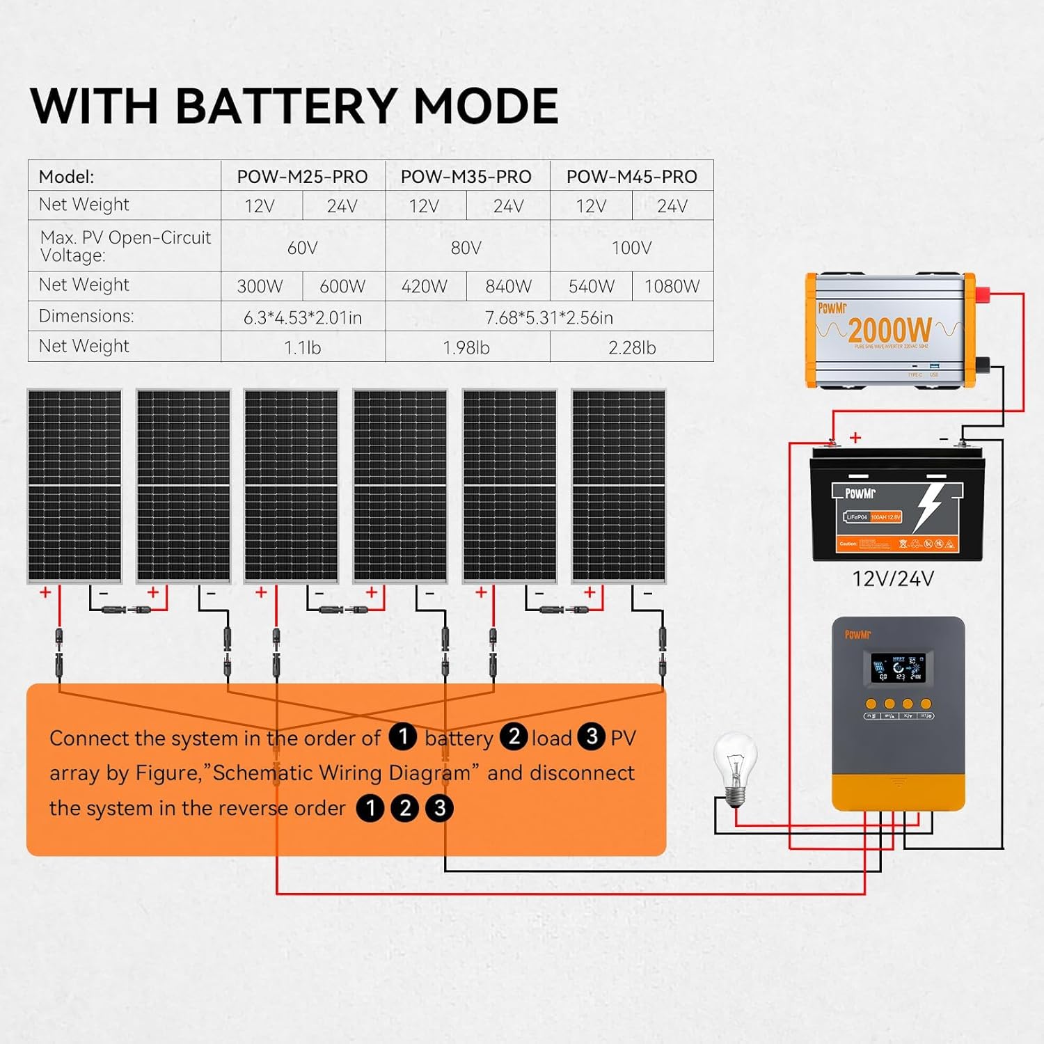
Figure 4.2: Schematic wiring diagram illustrating connections for solar panels, battery, inverter, and DC load. Connect in order: battery, load, PV array. Disconnect in reverse order.
5. Operating Instructions
5.1 LCD Display and Buttons
The controller features a detailed LCD screen and four buttons for monitoring and configuration. The buttons are typically labeled PV, BAT/▲, DC/▼, and SET/⚙️.
5.2 Battery Type Selection
The controller supports various battery types. To select or customize battery parameters:
- Long press the BAT/▲ key to enter the setting program.
- Use the BAT/▲ and DC/▼ keys to toggle through the battery type options.
- Press the SET/⚙️ key to save and confirm your selection.
- If 'User-defined' battery type is selected, proceed to set absorption voltage, float voltage, low voltage cutoff, and other parameters as needed.

Figure 5.1: Illustration of battery compatibility and selection process for various 12V/24V battery types.
5.3 Multiple Load Work Modes
The controller offers several load operating modes to manage connected DC loads:
- 00H (Load Turn OFF): The load output is always off.
- 24H (Load always Turn ON): The load output is continuously on.
- 01H~23H (Time control): The load output is controlled by a timer, allowing you to set the duration for which the load remains on.

Figure 5.2: Display of available load work modes for managing DC output.
5.4 Battery Voltage Calibration
If there is a discrepancy between the battery voltage monitored by the controller and a multimeter reading, you can calibrate the controller's voltage reading:
- Long press the BAT/▲ key to enter the setting program.
- Use the BAT/▲ and DC/▼ keys to adjust the displayed voltage value to match the multimeter reading.
- Press the SET/⚙️ key to save and confirm the calibration.

Figure 5.3: Instructions for calibrating the battery voltage reading on the LCD screen.
6. Maintenance
Regular maintenance ensures optimal performance and longevity of your solar charge controller.
- Check Connections: Periodically inspect all wiring connections for tightness and corrosion.
- Clean the Controller: Keep the controller clean and free from dust. Use a dry cloth for cleaning.
- Ventilation: Ensure the installation area remains well-ventilated to prevent overheating.
- Battery Inspection: Regularly check battery terminals for corrosion and ensure proper electrolyte levels for flooded batteries.
7. Troubleshooting
The controller's LCD screen displays working modes and error codes to assist in troubleshooting. Refer to the table below for common fault codes and their solutions.

Figure 7.1: LCD screen displaying working mode and a troubleshooting guide with fault codes and corresponding solutions.
Common Fault Codes and Solutions:
| Fault Code | Fault Cause | Solution |
|---|---|---|
| 18 | Input photovoltaic voltage too low | Increase the number of solar panels or connect them in series to raise the photovoltaic input voltage. |
| 60 | Overtemperature protection | Allow the equipment to cool to below the recovery temperature to resume normal charging and discharging. |
| 63 | Battery voltage too high | Measure to confirm if battery voltage exceeds rated voltage and disconnect photovoltaic array circuit breaker. |
| 65 | Battery voltage too low | Charge the battery until voltage exceeds the undervoltage recovery point. Refer to '5.2 Battery Type Selection' for specific details. |
| 71 | Input photovoltaic voltage too high | Reduce the number of photovoltaic arrays connected to the controller to lower photovoltaic input, or adjust series and parallel connections to reduce voltage or current values. |
| 73 | Overcharging current | Reduce output terminal load to ensure total load is within rated limits of the controller and battery. |
| 72 | Overdischarging current | Reduce output terminal load to ensure total load is within rated limits of the controller and battery. |
8. Specifications
Technical specifications for the PowMr 25A MPPT Solar Charge Controller.
| Specification | Value |
|---|---|
| Model | POW-M25-PRO |
| System Voltage | 12V / 24V Auto |
| Max PV Input Power (12V Battery) | 300W |
| Max PV Input Power (24V Battery) | 600W |
| Max PV Open-Circuit Voltage | <60V |
| Rated Charge Current | 25A |
| Battery Type Compatibility | Lead-acid (Sealed, Gel, Flooded), Lithium (LiFePO4, Lithium-ion) |
| Display Type | LCD |
| Material | Metal, Plastic |
| Dimensions | 6.3" x 4.53" x 2.01" (160mm x 115mm x 51mm) |
| Net Weight | 1.1 lb (0.5 kg) |
9. Warranty and Support
For warranty information, please refer to the documentation provided with your purchase or contact the seller directly. PowMr offers fast service support and detailed wiring instructions. For technical assistance or inquiries, please reach out to PowMr customer service.


