1. Introduction
Thank you for choosing the Viodmss MS5902R Circuit Breaker Finder and Socket Tester. This device is designed to quickly and accurately identify the correct circuit breaker or fuse protecting a specific electrical outlet. It also functions as a socket tester to verify proper wiring of electrical outlets. Please read this manual thoroughly before use to ensure safe and efficient operation.
2. Safety Information
WARNING: Electrical shock hazard. Always exercise extreme caution when working with electricity.
- Do not use the device if it appears damaged or is not functioning correctly.
- Ensure the voltage of the circuit being tested does not exceed the device's maximum operating voltage (250V AC).
- Always wear appropriate personal protective equipment (PPE), such as insulated gloves and safety glasses.
- Do not attempt to open or modify the device. There are no user-serviceable parts inside.
- Keep the device away from water and moisture.
- This device is intended for use by qualified personnel or under the supervision of a qualified electrician.
- Before performing any work on electrical circuits, always verify that the power is off using a known working voltage tester.
3. Product Overview
The Viodmss MS5902R consists of two main components: the Receiver and the Transmitter (Socket Tester).

Figure 3.1: Components of the MS5902R Circuit Breaker Finder and Socket Tester.
- Receiver:
- Inductive Head: Used to detect the signal from the circuit breaker.
- Low Voltage Indicator Light: Illuminates when battery power is low.
- NC V Indicator Light: Non-Contact Voltage detection indicator.
- Transfer Switch: Selects between different detection modes.
- S Switch: Sensitivity adjustment or function button.
- Indicator Light: Provides visual feedback during operation.
- Transmitter (Socket Tester):
- Indicator Lights (TONE/PULSE): Display wiring status.
- Transfer Switch: Selects between TONE and PULSE modes for circuit breaker finding.
- Socket Test Legend: Explains the meaning of the indicator light patterns for socket wiring.
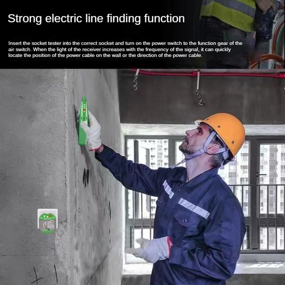
Figure 3.2: The Viodmss MS5902R Circuit Breaker Finder and Socket Tester with carrying case.
4. Setup
- Battery Installation (Receiver): Open the battery compartment on the back of the receiver and insert the required batteries (typically 9V, check device markings if unsure), observing correct polarity. Close the compartment securely.
- Initial Check: Before use, ensure both the receiver and transmitter are clean and free from damage.
5. Operating Instructions
5.1. Circuit Breaker Finding
This function helps identify which circuit breaker controls a specific outlet.
- Plug in the Transmitter: Insert the Transmitter (socket tester) into the electrical outlet you wish to identify the circuit breaker for.
- Select Mode on Transmitter: Use the Transfer Switch on the Transmitter to select either "TONE" or "PULSE" mode. "TONE" mode typically provides a continuous signal, while "PULSE" mode provides an intermittent signal. Experiment to see which works best in your environment.
- Activate Receiver: Turn on the Receiver. Adjust its sensitivity using the 'S' switch if available, or by cycling through modes with the Transfer Switch, until it is responsive but not overly sensitive.
- Scan Circuit Breakers: Go to your electrical panel. Slowly move the inductive head of the Receiver along the circuit breakers.
- Identify Breaker: The Receiver will emit an audible tone and/or illuminate its indicator lights more intensely when it detects the signal from the correct circuit breaker. The frequency or intensity of the signal will increase as you get closer to the correct breaker.
- Verify: Once a breaker is identified, turn it off. Return to the outlet and check if the power is off. If the power is off, you have found the correct breaker.
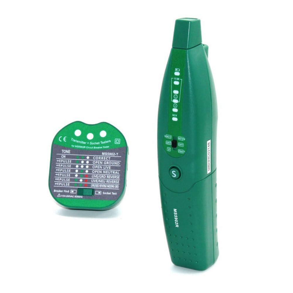
Figure 5.1: Using the receiver to locate electrical lines or circuit breakers.
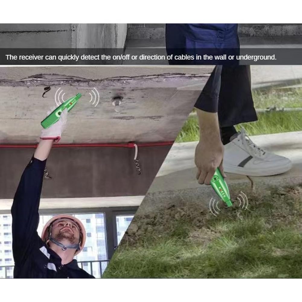
Figure 5.2: The receiver's capability to detect cables in walls or underground.
5.2. Socket Wiring Test
The Transmitter (socket tester) can also be used independently to check the wiring status of an electrical outlet.
- Plug in the Transmitter: Insert the Transmitter directly into the electrical outlet you want to test.
- Observe Indicator Lights: The indicator lights on the Transmitter will illuminate in specific patterns to indicate the wiring status.
- Interpret Results: Refer to the "Socket Test Legend" printed on the Transmitter (or Figure 3.1 in this manual) to understand the meaning of the light patterns. Common indications include:
- Correct: Wiring is correct.
- Open Ground: Ground wire is not connected.
- Open Neutral: Neutral wire is not connected.
- Open Live: Live (hot) wire is not connected.
- Live/Neutral Reverse: Live and Neutral wires are swapped.
- Live/Ground Reverse: Live and Ground wires are swapped.
- Action: If an incorrect wiring pattern is indicated, consult a qualified electrician to rectify the issue before using the outlet.
6. Maintenance
- Cleaning: Wipe the device with a dry, soft cloth. Do not use abrasive cleaners or solvents.
- Storage: Store the device in a cool, dry place, away from direct sunlight and extreme temperatures. If storing for extended periods, remove the batteries from the receiver to prevent leakage.
- Battery Replacement: Replace batteries in the receiver when the low voltage indicator light illuminates.
7. Troubleshooting
| Problem | Possible Cause | Solution |
|---|---|---|
| Receiver does not turn on. | Dead or incorrectly installed batteries. | Check battery polarity; replace batteries. |
| No signal detected by receiver during breaker finding. | Transmitter not plugged in or not in TONE/PULSE mode; receiver sensitivity too low; circuit is dead. | Ensure transmitter is correctly plugged in and set; increase receiver sensitivity; verify power to the outlet with another tester. |
| Receiver detects multiple breakers or no clear signal. | Receiver sensitivity too high; interference from other wiring. | Decrease receiver sensitivity; move receiver slowly and deliberately; try TONE vs. PULSE mode. |
| Socket tester shows incorrect wiring. | Actual wiring fault in the outlet. | Consult a qualified electrician to inspect and repair the wiring. Do not use the outlet until repaired. |
8. Specifications
| Feature | Detail |
|---|---|
| Model | MS5902R |
| Brand | Viodmss |
| Minimum Operating Voltage | 110 Volts AC |
| Maximum Operating Voltage | 250 Volts AC |
| Product Dimensions (L x W x H) | 24.5 x 6.8 x 14.5 cm (9.65 x 2.68 x 5.71 inches) |
| ASIN | B0DFY43M1M |
| Manufacturer | Viodmss |
9. Warranty & Support
For warranty information and technical support, please refer to the documentation included with your purchase or contact Viodmss customer service through their official website or the retailer where the product was purchased. Keep your proof of purchase for warranty claims.