1. Introduction
Thank you for choosing the IPUDIS SSR-41FDD Solid State Relay. This manual provides essential information for the safe and efficient installation, operation, and maintenance of your device. Please read this manual thoroughly before use and retain it for future reference.
2. Safety Information
WARNING: Electrical shock hazard. Installation and maintenance should only be performed by qualified personnel.
- Always disconnect power before installing, wiring, or servicing the relay.
- Ensure all wiring complies with local and national electrical codes.
- Do not exceed the specified voltage and current ratings of the relay.
- Proper heat sinking may be required for high current applications to prevent overheating.
- Avoid touching terminals when power is applied.
3. Product Overview
The IPUDIS SSR-41FDD is a DC-controlled solid-state relay designed to switch AC loads. It features an LED indicator for operational status and is rated for 6A. Solid-state relays offer fast switching, long life, and silent operation compared to traditional electromechanical relays.
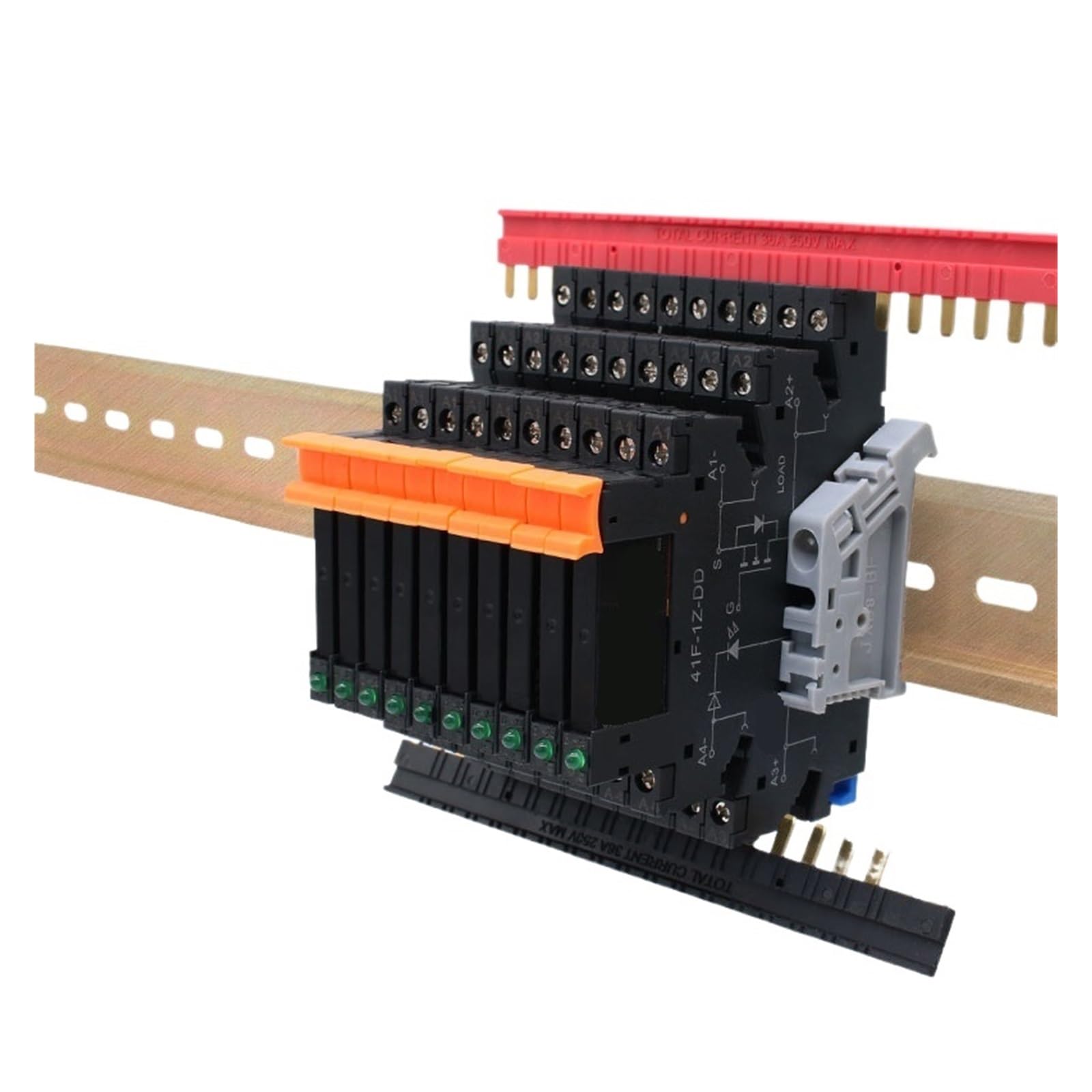
Figure 1: IPUDIS SSR-41FDD Solid State Relay. This image shows the compact design of the relay with input and output terminals clearly visible, along with the LED indicator.
3.1 Key Components
- Input Terminals: Used to connect the DC control signal. Typically labeled '+' and '-'.
- Output Terminals: Used to connect the AC load. Typically labeled 'L' and 'N' or 'A' and 'B'.
- LED Indicator: Illuminates when the control signal is applied and the relay is activated.
4. Setup and Wiring
Follow these steps for proper installation and wiring of the SSR-41FDD relay.
4.1 Mounting
Mount the relay in a location that allows for adequate ventilation. For loads approaching the maximum current rating, consider mounting the relay on a heat sink to dissipate heat effectively and prevent thermal damage.
4.2 Wiring Instructions
The SSR-41FDD requires a DC control voltage to switch an AC load. Refer to the following wiring guidelines:
- Control Input Wiring: Connect your DC control voltage source to the input terminals. Ensure correct polarity: connect the positive (+) terminal of your DC source to the '+' terminal of the relay, and the negative (-) terminal of your DC source to the '-' terminal of the relay. The control voltage range is typically 3-32VDC.
- Load Output Wiring: Connect the AC load to the output terminals. The relay acts as a switch in series with one leg of your AC load. For example, connect the AC line (L) through one output terminal of the relay, and the other output terminal to your AC load. The neutral (N) of your AC source connects directly to the other side of your AC load.
- Verify Connections: Double-check all wiring for correctness and secure connections before applying power. Loose connections can cause overheating or malfunction.
Note: Always ensure the load current and voltage are within the relay's specified limits (e.g., 6A AC output).
5. Operating Instructions
Once the SSR-41FDD is correctly wired and mounted, follow these steps for operation:
- Apply Power to Load: Energize the AC power source connected to your load circuit.
- Apply Control Signal: Apply the specified DC control voltage (e.g., 3-32VDC) to the input terminals of the relay.
- Observe LED Indicator: The built-in LED indicator on the relay should illuminate when the DC control signal is applied, indicating that the relay is activated and the AC load should be receiving power.
- Remove Control Signal: When the DC control signal is removed, the LED indicator will turn off, and the relay will switch off the AC load.
6. Maintenance
The SSR-41FDD is designed for long-term, maintenance-free operation. However, periodic inspection is recommended to ensure optimal performance and safety.
- Visual Inspection: Periodically check the relay for any signs of physical damage, discoloration, or loose connections.
- Cleaning: If necessary, gently clean the exterior of the relay with a dry, soft cloth. Do not use solvents or abrasive cleaners.
- Environmental Conditions: Ensure the operating environment remains within the specified temperature and humidity ranges. Excessive heat or moisture can affect performance and lifespan.
7. Troubleshooting
If you encounter issues with your SSR-41FDD, refer to the following troubleshooting guide:
| Problem | Possible Cause | Solution |
|---|---|---|
| Relay does not switch ON (LED off) | No DC control voltage; Incorrect control voltage polarity; Control voltage too low; Faulty relay. | Verify DC control voltage presence and level; Check polarity; Replace relay if faulty. |
| Relay does not switch OFF | Control voltage not removed; Load current too low (for some AC SSRs); Faulty relay. | Ensure DC control voltage is completely removed; Verify minimum load current if applicable; Replace relay if faulty. |
| Load not receiving power (LED ON) | No AC power to load; Open circuit in load wiring; Overload protection tripped; Faulty relay. | Check AC power source; Inspect load wiring; Check for tripped breakers/fuses; Replace relay if faulty. |
| Relay overheats | Exceeding current rating; Insufficient heat sinking; Poor ventilation. | Reduce load current; Install appropriate heat sink; Improve ventilation around the relay. |
8. Specifications
The following table outlines the technical specifications for the IPUDIS SSR-41FDD Solid State Relay:
| Feature | Specification |
|---|---|
| Model Number | SSR-41FDD |
| Control Type | DC Control DC |
| Input Control Voltage | 3-32V DC (typical) |
| Output Load Voltage | AC (specific range not provided, typically 24-380VAC for similar models) |
| Output Load Current | 6A |
| Indicator | LED (for status) |
| Package Dimensions | 1.18 x 0.79 x 0.39 inches |
| Item Weight | 1.76 ounces |
| Manufacturer | IPUDIS |
9. Warranty and Support
For warranty information and technical support, please refer to the documentation provided with your purchase or contact IPUDIS directly through their official website or customer service channels. Specific warranty terms may vary by region and retailer.