1. Introduction and Overview
The POCREATION Router Lift System Kit is designed to provide precise and effortless height adjustment for your router when mounted in a router table. Constructed from durable aluminum alloy and stainless steel, this system ensures stability and longevity for various woodworking applications. It features a manual lifting mechanism with a crank handle, allowing for fine adjustments of the router bit height from above the table surface.
This router lift is compatible with trimming machines having a motor diameter between 64mm and 66mm and supports a maximum lifting stroke of 51mm. Its robust design prevents slippage, enhancing work efficiency and accuracy in your woodworking projects.

Image 1.1: Fully assembled POCREATION Router Lift System Kit, showing the top plate, lifting mechanism, and crank handle.
2. Safety Information
Always prioritize safety when working with power tools and woodworking equipment. Failure to follow safety guidelines can result in serious injury.
- Read and understand the instruction manual for your router and router table before operating this lift system.
- Wear appropriate personal protective equipment (PPE), including safety glasses, hearing protection, and dust masks.
- Ensure the router lift is securely installed in your router table and the router is firmly clamped before use.
- Disconnect power to the router before making any adjustments, changing bits, or performing maintenance.
- Keep hands and fingers clear of the router bit and moving parts during operation.
- Maintain a clean and well-lit work area to prevent accidents.
3. Package Contents
Verify that all components are present and undamaged upon opening the package. If any parts are missing or damaged, contact customer support.
- 1 x Woodworking Base (Router Lift Top Plate)
- 1 x Handle (Crank Handle)
- 4 x Screw (Mounting Screws)
- 1 x Hex Wrench
- 1 x Flip Board (Router Mounting Plate)
- 2 x Insert Ring (Router Bit Opening Reducers)
4. Specifications
| Feature | Specification |
|---|---|
| Item Type | Router Lifting Base |
| Material | Aluminum alloy, Stainless steel |
| Panel Material | Aluminum Alloy |
| Table Size | Approx. 240 x 200mm / 9.45 x 7.87in |
| Maximum Lifting Stroke | Approx. 51mm / 2.01in |
| Lifting Method | Manual lifting, with manual lifting lever |
| Installation Screw Hole Position | Approx. 70 x 62mm / 2.76 x 2.44in |
| Applicable Trimming Machine | Universal type, suitable for trimming machines with motor diameter between 64 ~ 66mm / 2.52 ~ 2.6in |
| Item Weight | Approx. 2.97 pounds |
| Color | Gold |
5. Setup Instructions
5.1 Installing the Router into the Flip Board
- Ensure your router is unplugged from the power source.
- Remove the base plate from your router.
- Align your router with the pre-drilled holes on the provided 'Flip Board' (router mounting plate). The Flip Board is designed to accommodate routers with motor diameters between 64mm and 66mm.
- Secure the router to the Flip Board using appropriate screws (not included, typically supplied with your router or available separately). Ensure a tight and stable connection.
5.2 Installing the Router Lift into a Router Table
- Prepare your router table by ensuring it has an opening compatible with the router lift's woodworking base (approx. 240 x 200mm).
- Place the assembled router and Flip Board onto the lifting mechanism of the router lift.
- Carefully lower the entire router lift assembly into the opening of your router table.
- Align the mounting screw holes on the router lift's woodworking base with the corresponding holes on your router table. The installation screw hole position is approximately 70 x 62mm.
- Secure the router lift to the router table using the four provided screws and the hex wrench. Tighten securely to prevent movement during operation.
- Insert the crank handle into the designated opening on the top plate.
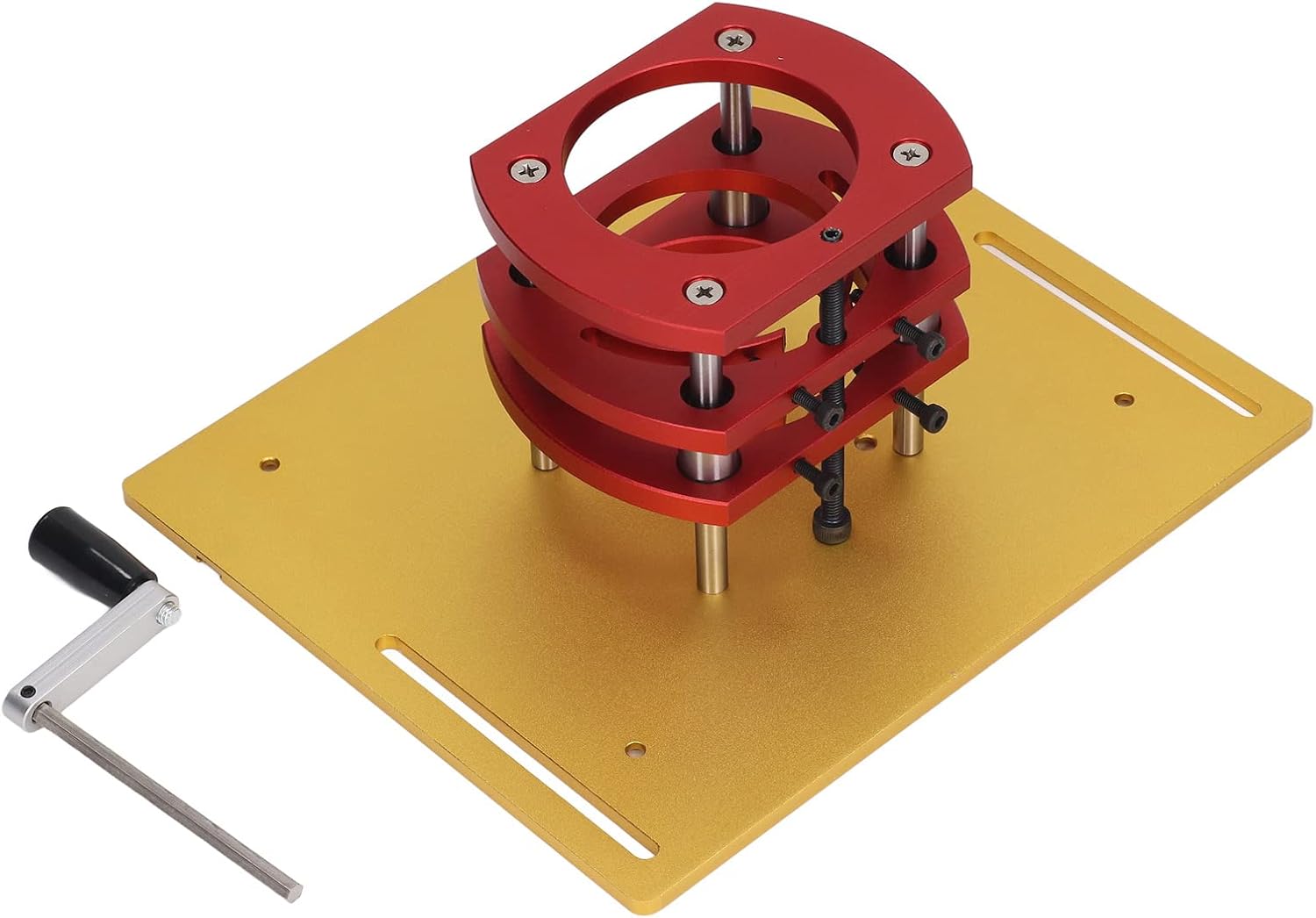
Image 5.1: Underside view of the router lift, illustrating the red lifting mechanism and the gold flip board where the router attaches.
6. Operating Instructions
6.1 Adjusting Router Bit Height
- Ensure the router is securely mounted and the router lift is firmly installed in your router table.
- Select the appropriate router bit and install it into your router's collet, following your router's instructions.
- Insert the crank handle into the access hole on the top plate of the router lift.
- Rotate the crank handle clockwise to raise the router bit or counter-clockwise to lower it. Make small, controlled adjustments.
- Use a depth gauge or ruler to accurately set the desired bit height. The top plate may include measurement markings for reference.
- Once the desired height is achieved, remove the crank handle.
6.2 Using Insert Rings
The kit includes two insert rings to reduce the size of the router bit opening on the top plate. Select the insert ring that provides the smallest possible opening around your router bit while allowing for proper chip evacuation. This helps improve dust collection and provides better support for smaller workpieces.

Image 6.1: Top view of the router lift, highlighting the crank handle in position for height adjustment and the integrated measurement scales.
7. Maintenance
Regular maintenance ensures the longevity and optimal performance of your router lift system.
- Cleaning: After each use, clean the router lift and surrounding area to remove sawdust and debris. Use a brush or compressed air. Avoid using harsh chemicals that could damage the finish or materials.
- Lubrication: Periodically apply a small amount of dry lubricant (e.g., PTFE spray) to the lifting screw and guide rods to ensure smooth operation. Do not over-lubricate, as this can attract dust.
- Inspection: Regularly inspect all screws and fasteners for tightness. Check for any signs of wear or damage to the aluminum alloy and stainless steel components. Replace any worn or damaged parts immediately.
- Storage: When not in use, store the router lift in a clean, dry environment to prevent corrosion and damage.

Image 7.1: Side view of the router lift, illustrating the threaded rod and support pillars that facilitate the lifting action.
8. Troubleshooting
If you encounter issues with your router lift, refer to the following common troubleshooting steps:
| Problem | Possible Cause | Solution |
|---|---|---|
| Difficulty in lifting/lowering router | Accumulation of dust/debris on lifting screw or guide rods; lack of lubrication; binding components. | Clean the lifting mechanism thoroughly. Apply a dry lubricant to the screw and rods. Check for any obstructions. |
| Router lift feels unstable or wobbly | Mounting screws are loose; router not securely attached to flip board; router table opening is too large. | Tighten all mounting screws for the lift and the router. Ensure the router table opening provides adequate support. |
| Router bit height not holding position | Lifting mechanism components are worn or damaged; insufficient friction. | Inspect the lifting mechanism for wear. If components are damaged, contact customer support for replacement parts. |
9. Warranty Information
Specific warranty details for the POCREATION Router Lift System Kit are not provided in this manual. For information regarding warranty coverage, terms, and conditions, please refer to the product packaging or contact POCREATION customer support directly. Keep your proof of purchase for any warranty claims.
10. Support
For further assistance, technical support, or to inquire about replacement parts, please contact POCREATION customer service. You may also visit the official POCREATION store on Amazon for additional product information and resources: