Introduction
This user manual provides comprehensive instructions for the FAUOSWUK Stepper Motor Driver and PWM Controller. This versatile board is designed to generate PWM signals and control stepper motors, offering flexible power options and precise control over motor speed and direction. Please read this manual thoroughly before operation to ensure proper usage and optimal performance.
Product Overview
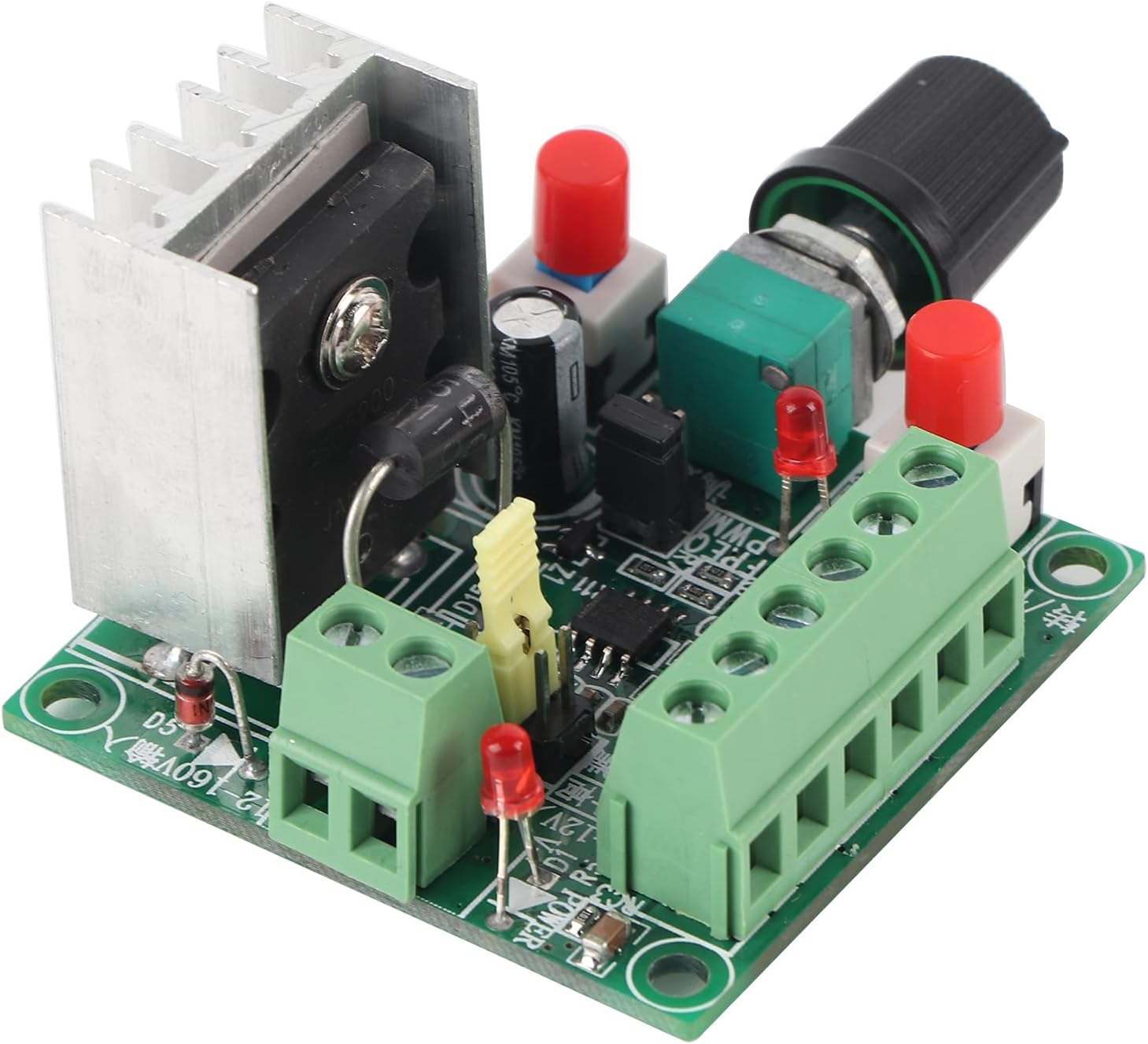

The FAUOSWUK Stepper Motor Driver and PWM Controller is a compact and efficient module designed for precise control of stepper motors. It features a PWM signal generator with selectable frequency ranges (high, mid, low), a potentiometer for speed adjustment, and switches for controlling motor direction and start/stop functions. The board supports a wide input voltage range, making it adaptable to various applications.
Specifications
| Feature | Value |
|---|---|
| Input Voltage (High Range) | 15-160V DC |
| Input Voltage (Low Range) | 5-12V DC |
| High Frequency Range | 5.8KHZ - 127KHZ |
| Mid Frequency Range | 590HZ - 15.8KHZ |
| Low Frequency Range | 82HZ - 2.3KHZ |
| Dimensions | Approx. 50 x 51 x 37mm (1.97 x 2 x 1.45 inches) |
| Weight | 50g (1.76 oz) |
| Model Number | FAUOSWUK7w9epdq6hb |

Setup and Installation
1. Power Supply Connection
The controller supports two main power input ranges:
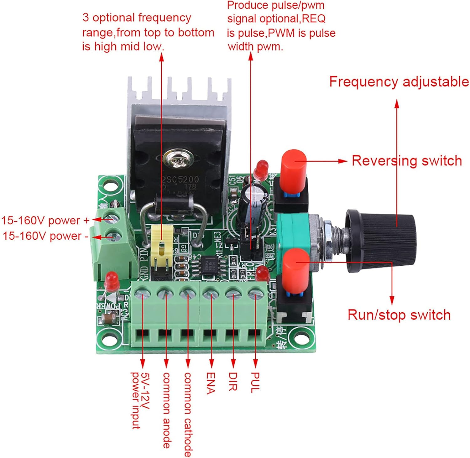
- High Voltage Input: 15-160V DC. Connect to the terminals labeled "15-160V power +" and "15-160V power -".
- Low Voltage Input: 5-12V DC. Connect to the terminals labeled "5-12V power input".
Ensure the correct polarity when connecting the power supply. Using an incorrect voltage or reversed polarity can damage the device.
2. Stepper Motor Driver Connection
The module provides six terminals for connecting to a stepper motor driver:
- PUL (Pulse): Connect to the pulse input of your stepper motor driver. This terminal outputs the PWM signal.
- DIR (Direction): Connect to the direction input of your stepper motor driver. This terminal controls the motor's rotation direction.
- ENA (Enable): Connect to the enable input of your stepper motor driver. This terminal enables or disables the motor driver.
- Common Anode / Common Cathode: These terminals are for connecting the common anode or common cathode of your stepper motor driver, depending on its configuration. Refer to your driver's manual for the correct connection.
Important Note: If you intend to use the start or stop function, the ENA controller enable terminal must be connected to either the common cathode or common anode of your drive, as per your specific driver's requirements.
Operating Instructions
1. Frequency Selection
The board features a jumper for selecting the pulse frequency signal. There are three optional frequency ranges:
- High Frequency: 5.8KHZ - 127KHZ
- Mid Frequency: 590HZ - 15.8KHZ
- Low Frequency: 82HZ - 2.3KHZ
Adjust the jumper position to select the desired frequency range for your application. The specific jumper settings are usually indicated on the PCB itself or in a detailed wiring diagram.
2. Speed Adjustment
The motor speed can be finely tuned using the potentiometer on the board. Rotate the knob clockwise to increase the pulse frequency (and thus motor speed) and counter-clockwise to decrease it.
3. Direction Control
A dedicated reversing switch allows for easy adjustment of the motor's forward and reverse rotation. Toggle this switch to change the direction of the stepper motor.
4. Start/Stop Function
The run/stop switch controls the activation and deactivation of the pulse output. Press this switch to start or stop the motor's operation. Remember to ensure the ENA terminal is correctly wired for this function to work.
Maintenance
The FAUOSWUK Stepper Motor Driver and PWM Controller is designed for durability and requires minimal maintenance. However, regular checks can prolong its lifespan and ensure reliable operation:
- Keep Clean: Periodically clean the board to remove dust and debris, which can affect performance or cause short circuits. Use a soft, dry brush or compressed air.
- Inspect Connections: Ensure all wire connections to the terminal blocks are secure and free from corrosion. Loose connections can lead to intermittent operation or damage.
- Ventilation: Ensure adequate airflow around the heatsink, especially during prolonged operation, to prevent overheating.
- Storage: When not in use, store the module in a dry, cool environment away from direct sunlight and extreme temperatures.
Troubleshooting
| Problem | Possible Cause | Solution |
|---|---|---|
| No power indicator light | Incorrect power supply voltage or polarity; loose power connection. | Verify power supply voltage (15-160V DC or 5-12V DC) and polarity. Check power terminal connections. |
| Motor not moving | Incorrect wiring to stepper driver (PUL, DIR, ENA); ENA not connected correctly for start/stop; motor driver issue; no pulse output. | Check all connections to the stepper motor driver. Ensure ENA is connected to common anode/cathode if using start/stop. Verify the motor driver is functioning correctly. Check frequency selection. |
| Motor speed not adjustable | Potentiometer fault; incorrect frequency range selected. | Ensure the potentiometer is not damaged. Verify the frequency jumper setting is appropriate for the desired speed range. |
| Motor direction not changing | Reversing switch fault; DIR terminal not correctly wired to driver. | Check the reversing switch for proper function. Confirm the DIR terminal is correctly connected to the stepper driver. |
Warranty and Support
FAUOSWUK products are manufactured to high-quality standards. For any issues or technical support, please contact your retailer or visit the official FAUOSWUK store on Amazon for assistance. Please refer to your purchase documentation for specific warranty terms and conditions.
For further information or to explore other products, visit the FAUOSWUK Store on Amazon.