1. Setup
1.1 Install Vibration-Damping Base
Install the pump's vibration-damping base to ensure stability during operation. Secure it firmly with the provided wrench.
Video: Installation of the vibration-damping base for the gasoline engine water pump.
1.2 Add Engine Oil
Unscrew the oil dipstick and add engine oil. The required amount is approximately 0.5 liters (500 ml). Ensure the oil level is between the 'H' (maximum) and 'L' (minimum) marks on the dipstick. Insufficient oil will prevent the pump from starting and may damage the engine. Change the oil after the first 20 hours of operation or one month, and then every 50 hours thereafter.
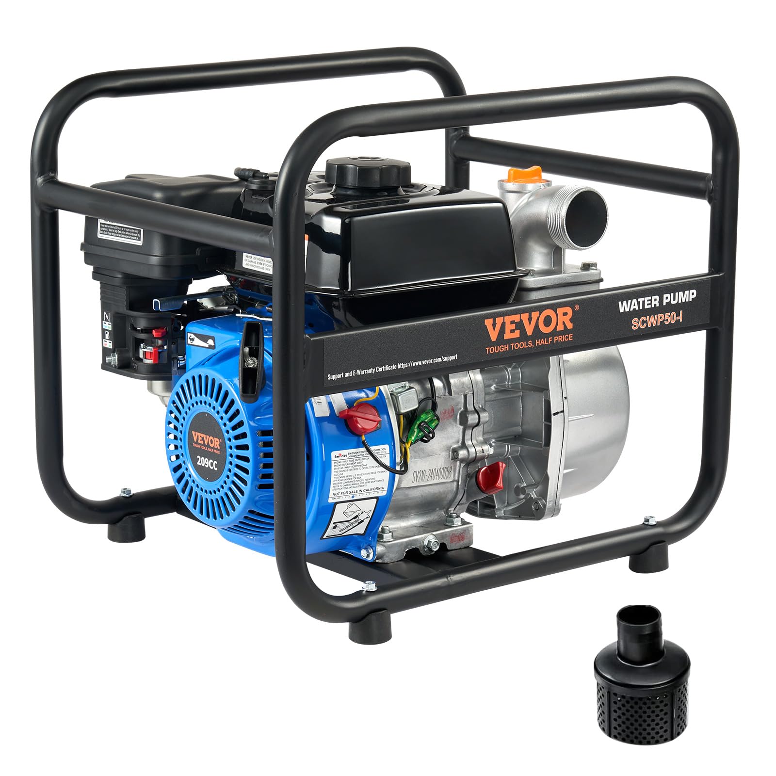
Image: VEVOR 6.5HP Gasoline Powered Trash Pump, showing the location of the oil dipstick.
1.3 Fill Fuel Tank with Gasoline
Fill the fuel tank with unleaded gasoline. The tank capacity is 3 liters. Ensure the fuel cap is securely tightened after filling.
1.4 Install Outlet Hose
Connect the outlet hose to the pump unit. Place the sealing gasket flat onto the pump connector, then attach the hose and tighten the hose clamp securely. Ensure all connections are secure and airtight to prevent leaks.
1.5 Install Inlet Hose
Connect the inlet hose to the pump unit. Install the filter screen at the end of the inlet hose to prevent large debris from being sucked in and damaging the pump. Use a plastic hose for the inlet connection; fabric-reinforced hoses are not suitable. Ensure the clamp is fully tightened, as a loose clamp will cause air leaks and prevent the pump from priming. The maximum suction lift for this pump is 7 meters. Exceeding this vertical distance will prevent the pump from drawing water.
1.6 Priming the Pump
Unscrew the priming port cap on the top of the pump. Fill the pump body completely with water until water flows out from the outlet. This indicates the pump is fully primed. Insufficient priming water will result in the pump's inability to draw water. Tighten the priming port cap securely after filling.
2. Operation
2.1 Starting the Engine
- Turn the fuel valve to the "ON" position.
- Set the choke to the "START" position. (Use the choke when starting a cold engine. If restarting the engine while it is still warm, the choke may not be needed.)
- Ensure the ignition switch is in the "ON" position.
- Firmly hold the starter handle and pull the cord briskly to start the engine.
- Once the engine starts, gradually move the choke to the "RUN" position.
- Move the throttle to the maximum position to achieve full engine power for pumping.
Video: Step-by-step guide on starting the gasoline engine water pump.
2.2 General Operation Guidelines
Always ensure the pump chamber is fully primed with water before starting the engine. Do not operate the pump in or near water to prevent electrical hazards and damage to the unit.

Image: VEVOR gasoline engine water pump actively used for irrigation.
3. Maintenance
3.1 Engine Oil Maintenance
Change the engine oil after the first 20 hours of operation or one month, whichever comes first. Subsequently, change the oil every 50 hours of operation.
3.2 Air Cleaner Maintenance
Clean the air cleaner element every 50 hours of operation, or every 10 hours if operating in dusty conditions. To clean, wash the element in a high flash point solvent, squeeze it dry, then dip it in clean engine oil and squeeze out any excess oil before reinstallation.

Image: Detailed view of the VEVOR gasoline engine, highlighting the air cleaner for maintenance.
4. Troubleshooting
Video: Troubleshooting common issues with the gasoline engine water pump.
4.1 Equipment Fails to Start
- Check Gasoline: Ensure gasoline has been added to the fuel tank.
- Check Engine Oil: Verify that the engine oil level is at the middle mark on the dipstick. The oil capacity is 600 ml.
- Ignition Switch: Confirm the ignition switch is in the "ON" position.
- Spark Plug: Check if the spark plug is igniting properly. Use the provided spark plug wrench to remove the spark plug. Connect the igniter and ground it against a metal surface; a visible spark indicates normal operation.
- Fuel Valve: Ensure the fuel valve is in the "ON" position.
- Fuel Line: Check if the fuel line is clear. Remove the bolt at the bottom of the carburetor and check for fuel flow. Also, inspect the fuel hose connected to the carburetor for any kinks.
4.2 Equipment Fails to Pump Water During Operation
- Pump Priming: Check if the pump chamber has been filled with priming water. Continue filling until water flows out from the water outlet.
- Sealing & Connections: Check that the rubber O-rings on the inlet and outlet pipe connections are properly sealed and seated. Also, ensure the hose connections are secure and airtight.
- Hose Type: Use a plastic hose, not a fabric hose, for the water inlet connection.
- Suction Lift: Ensure the suction lift does not exceed 7 meters.
4.3 Equipment Emits White Smoke During Operation
- Engine Piston Rings: Check for worn engine piston rings, which can cause white smoke by burning oil.
- Engine Oil Overfill: Check for overfilling of engine oil, which can also lead to oil burning and white smoke.
- Starter Assembly: Remove the starter assembly bolts and check if the starter is jammed by foreign objects.
- Water Pump Housing: Remove the bolts of the water pump housing and check if the internal impeller is jammed by foreign objects.
5. Specifications
| Model Number | SCWP50-I |
| Engine Type | 6.5HP 4-Stroke OHV Air-Cooled Gasoline Engine |
| Maximum Flow Rate | 132 Gallons Per Minute (GPM) |
| Maximum Lifting Height | 98 Feet |
| Maximum Suction Lift | 26 Feet |
| Inlet/Outlet Diameter | 2 inches (50 mm) |
| Impeller Material | Cast Iron |
| Gasoline Type | Unleaded Gasoline |
| Fuel Tank Capacity | 3 Liters |
| Engine Oil Capacity | 0.5 Liters |
| Item Weight | 22.5 Kilograms |
| Material | Aluminum, Cast Iron |
| Color | Red |
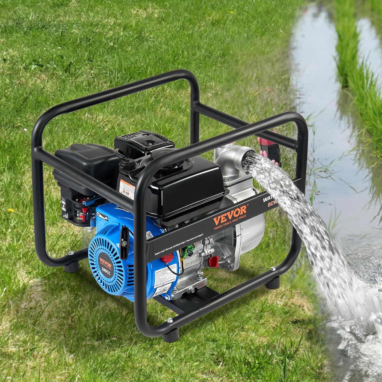
Image: Product dimensions and key specifications for the VEVOR water pump.
6. Warranty & Support
6.1 Warranty Information
Warranty information for this product is not available in the provided data. Please refer to your purchase documentation or contact the seller directly for details regarding warranty coverage.
6.2 Customer Support
Specific customer support contact information is not available in the provided data. For assistance, please refer to the contact details provided at the point of purchase or visit the official VEVOR website.


