1. Introduction
This manual provides essential information for the proper installation, operation, and maintenance of the L90-CSDC 12V 30A PCB Mountable Relay. Please read this manual thoroughly before using the product to ensure safe and efficient operation.
2. Product Overview
The L90-CSDC is a high-quality, PCB mountable, single-pole double-throw (SPDT) relay designed for controlling high current AC or DC loads with a low-power signal. Relays function as electrically operated switches, providing isolation between the control circuit and the load circuit. This specific model is capable of handling up to 12V DC voltage and 30 Amps of current, making it suitable for a wide range of industrial and scientific applications, including robotics.
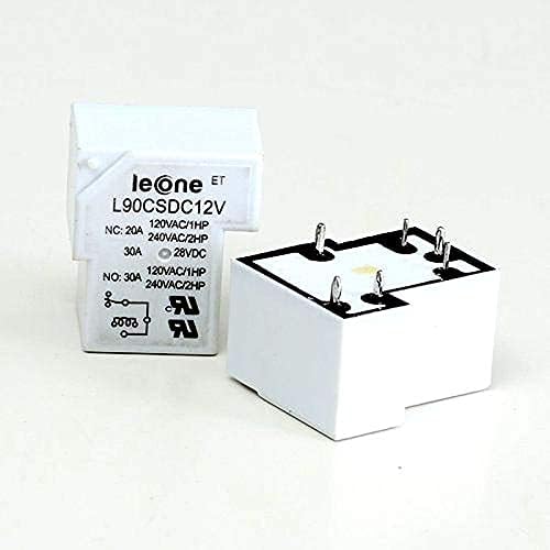
Figure 1: L90-CSDC 12V 30A PCB Mountable Relay. This image shows the white rectangular relay module with its pins visible on the underside, designed for mounting onto a Printed Circuit Board (PCB). The top surface displays the model number "L90CSDC12V" and electrical ratings.
3. Key Features
- Coil Voltage: 12 Volts DC
- Contact Current Rating: Up to 30 Amps
- Contact Configuration: SPDT (Single Pole Double Throw)
- Mounting Type: PCB Mountable (Chassis Mount)
- Material: Steel contacts
- Operation Mode: Automatic switching
4. Technical Specifications
| Specification | Value |
|---|---|
| Brand | Generic (Manufactured by iBAT Solutions) |
| Model Number | 5156468J GHCGDTR |
| Coil Voltage | 12 Volts DC |
| Current Rating | 30 Amps |
| Maximum Switching Current | 30 Amps |
| Maximum Switching Voltage | 12 Volts DC (also rated for AC loads as per product image: 120VAC/1HP, 240VAC/2HP) |
| Contact Type | Normally Closed (NC) and Normally Open (NO) - SPDT |
| Contact Material | Steel |
| Mounting Type | Chassis Mount (PCB Mountable) |
| Connector Type | Clamp (referring to the pins for PCB connection) |
| Product Dimensions (LxWxH) | 2 x 2 x 2 cm (20 x 20 x 20 Millimeters) |
| Item Weight | 2 g |
| Country of Origin | India |
5. Installation Guide
The L90-CSDC relay is designed for PCB (Printed Circuit Board) mounting. Proper installation is crucial for reliable operation and safety.
5.1. Safety Precautions
- Always disconnect power to the circuit before installing or removing the relay.
- Ensure that the relay's voltage and current ratings match or exceed the requirements of your application.
- Wear appropriate personal protective equipment (PPE), such as safety glasses.
- If you are unsure about any aspect of the installation, consult a qualified electrician or electronics technician.
5.2. Mounting on PCB
- Identify the correct pin orientation on your PCB. The relay has multiple pins for the coil and the contacts (Common, Normally Open, Normally Closed). Refer to the pinout diagram usually provided on the relay's datasheet or the relay body itself (as seen in Figure 1, showing NC, NO, and coil symbols).
- Carefully align the relay pins with the corresponding holes on the PCB.
- Gently push the relay into place until it sits flush with the PCB surface.
- Solder the relay pins to the PCB pads using appropriate soldering techniques. Ensure good solder joints for reliable electrical connection.
5.3. Wiring Connections
The L90-CSDC is an SPDT relay, meaning it has one common contact (COM), one normally open contact (NO), and one normally closed contact (NC), in addition to the coil terminals.
- Coil Terminals: Connect your 12V DC control signal across these terminals. When 12V DC is applied, the coil energizes.
- Common (COM) Terminal: This is the input for the circuit you want to switch.
- Normally Open (NO) Terminal: This contact is open (no connection) when the coil is de-energized and closes when the coil is energized.
- Normally Closed (NC) Terminal: This contact is closed (connected to COM) when the coil is de-energized and opens when the coil is energized.
Always verify the pinout on the relay itself or its datasheet for precise connections.
6. Operation Principles
A relay operates on the principle of electromagnetism. When an electrical current flows through the relay's coil, it generates a magnetic field. This magnetic field attracts an armature, causing it to move and change the state of the electrical contacts.
- De-energized State: When no voltage is applied to the 12V DC coil, the Common (COM) contact is connected to the Normally Closed (NC) contact. The Normally Open (NO) contact remains disconnected from COM.
- Energized State: When 12V DC is applied to the coil, the magnetic field pulls the armature. This causes the Common (COM) contact to disconnect from the Normally Closed (NC) contact and connect to the Normally Open (NO) contact.
This mechanism allows a low-power control signal (12V DC for the coil) to switch a much higher power circuit (up to 30 Amps AC or DC) safely and efficiently.
7. Maintenance and Care
The L90-CSDC relay is a robust electronic component designed for long-term reliability. Minimal maintenance is required, but following these guidelines can extend its lifespan:
- Keep Clean: Ensure the relay and its surrounding area are free from dust, dirt, and moisture. Use a soft, dry cloth for cleaning.
- Environmental Conditions: Operate the relay within its specified temperature and humidity ranges. Avoid extreme conditions.
- Avoid Overload: Do not exceed the maximum current and voltage ratings. Overloading can cause premature failure and safety hazards.
- Inspect Connections: Periodically check solder joints and wiring connections for looseness or corrosion, especially in high-vibration environments.
- Contact Wear: Over time, the contacts may experience wear, especially when switching inductive loads or high currents frequently. If erratic behavior or arcing is observed, the relay may need replacement.
8. Troubleshooting
If you encounter issues with your L90-CSDC relay, consider the following common troubleshooting steps:
| Problem | Possible Cause | Solution |
|---|---|---|
| Relay does not click/energize when control voltage is applied. |
|
|
| Load does not switch on/off. |
|
|
| Relay makes buzzing noise. |
|
|
9. Safety Information
Always adhere to general electrical safety practices when working with relays and electrical circuits:
- Never work on live circuits. Always disconnect power before making or breaking connections.
- Ensure proper insulation for all wires and connections.
- Use appropriate circuit protection (fuses, circuit breakers) for both the control and load circuits.
- Do not use the relay in environments where it may be exposed to flammable gases, liquids, or excessive moisture unless specifically rated for such conditions.
- Dispose of electronic waste responsibly according to local regulations.
10. Warranty and Support
For warranty information or technical support regarding your L90-CSDC 12V 30A PCB Mountable Relay, please contact the manufacturer, iBAT Solutions, or your point of purchase. Please have your model number (5156468J GHCGDTR) and purchase details ready when contacting support.
Manufacturer: iBAT Solutions
Country of Origin: India