OONO D-1003T Series
OONO DIN Rail Mount 16 LEDs Indicator Light Module
Model: D-1003T Series
Introduction
This manual provides comprehensive instructions for the installation, operation, and maintenance of your OONO DIN Rail Mount 16 LEDs Indicator Light Module. This module is designed for industrial and electrical applications, offering clear visual indication with 16 independent LED channels. Please read this manual thoroughly before use to ensure proper and safe operation.
Safety Information
- Always disconnect power before installing, wiring, or performing maintenance on the module.
- Ensure all wiring conforms to local and national electrical codes.
- This module operates with DC voltage. Verify correct polarity before applying power.
- Do not exceed the specified operating voltage range of 5VDC to 50VDC.
- Avoid exposing the module to excessive moisture, dust, or extreme temperatures.
- Only qualified personnel should perform installation and wiring.
Product Overview
The OONO D-1003T Series is a 16-channel LED indicator light module featuring 5mm blue LEDs. It supports both Common Positive and Common Negative control modes, making it versatile for various circuit designs. The module is equipped with 5.0mm pitch screw terminal blocks for secure wire connections and comes with a high-quality fireproof nylon DIN rail mount carrier.
Key Features:
- 16 independent LED indicator channels.
- Wide operating voltage range: 5VDC to 50VDC.
- Supports Common Positive and Common Negative control.
- Robust 5.0mm pitch screw terminal blocks.
- DIN rail mountable (35mm, 32mm, 15mm compatible) with detachable carrier for panel mounting.
- FR-4 fiber glass PCB for durability.
Components:
- 16 x 5mm Blue LEDs
- Input Terminal Blocks (Channels 1-8, 9-16, COM)
- DIN Rail Mount Carrier
- FR-4 PCB

Figure 1: Top-down view of the 16-LED indicator module, showing the LED array and terminal blocks.
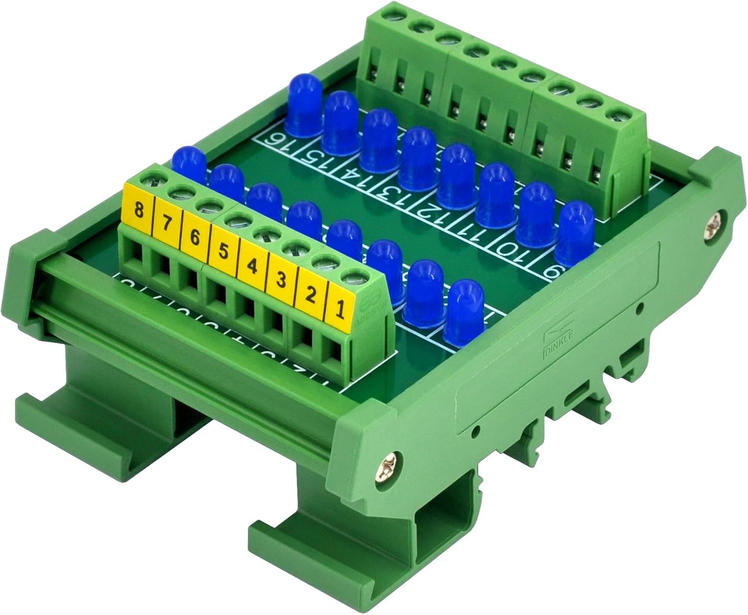
Figure 2: Angled perspective of the module, highlighting its compact design and integrated DIN rail mounting mechanism.
Specifications
| Parameter | Value |
|---|---|
| Model Number | D-1003T Series |
| Number of Channels | 16 |
| LED Color | Blue |
| LED Diameter | 5mm |
| Operating Voltage | 5VDC ~ 50VDC |
| Drive Current (per LED) | 0.3mA (at 5VDC), 1.0mA (at 12VDC), 2.2mA (at 24VDC), 4.6mA (at 48VDC) |
| Terminal Block Pitch | 5.0mm / 0.197" |
| Wire Range | 26 to 12AWG / 2.5mm² |
| Strip Length | 7mm / 0.28" |
| Mounting Type | DIN Rail Mount (35mm/32mm/15mm), Panel Mount (carrier detachable) |
| Material | Fireproof Nylon (carrier), FR-4 (PCB) |
| Product Dimensions | 3.42 x 2.44 x 1.58 inches (87 x 62 x 40.2 mm) |
| Item Weight | 4.3 ounces (122 grams) |
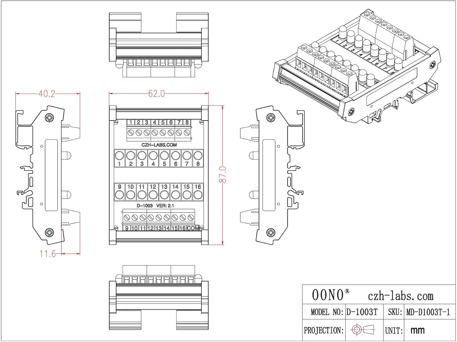
Figure 3: Detailed dimensional drawing of the module, showing key measurements in millimeters.
Setup and Installation
What's in the Box:
- 1 x DIN rail mount indicator light module
Mounting the Module:
The module is designed for easy installation on standard DIN rails (35mm, 32mm, or 15mm). The carrier can also be detached for panel mounting applications.
- DIN Rail Mounting: Align the module's clips with the DIN rail. Press down firmly until the module snaps securely onto the rail. Ensure it is seated properly and does not wobble.
- Panel Mounting: The DIN rail carrier can be disassembled from the main PCB. Once detached, the PCB can be mounted directly to a panel using appropriate standoffs or screws (not included).

Figure 4: The indicator module securely mounted on a standard DIN rail, ready for wiring.
Wiring Instructions:
The module features 5.0mm pitch screw terminal blocks for connecting input signals. Each LED channel (1-16) has a dedicated input terminal, and there is a common (COM) terminal.
- Prepare Wires: Strip approximately 7mm (0.28 inches) of insulation from the ends of your wires (26 to 12AWG / 2.5mm²).
- Connect Inputs: Loosen the screws on the desired terminal blocks. Insert the stripped wire ends fully into the terminal openings. Tighten the screws to secure the wires. Gently tug on the wires to ensure a firm connection.
- Common Connection: Connect the common return path of your control circuit to the "COM" terminal.

Figure 5: Close-up view of the screw terminal blocks, indicating channel numbers and the common terminal.
Operating Modes
The OONO D-1003T Series supports both Common Positive and Common Negative control configurations. This flexibility allows integration into various existing control systems.
Common Positive Control:
In this mode, the "COM" terminal is connected to the positive supply voltage. Each individual channel terminal (1-16) is then connected to the negative side of the control signal. When a channel's input is pulled low (connected to ground or negative supply), the corresponding LED will illuminate.
- Connect the positive supply (e.g., +5VDC to +50VDC) to the COM terminal.
- Connect the negative side of your control signal for each channel (1-16) to its respective input terminal.
- LED illuminates when the input terminal is connected to the negative potential.
Common Negative Control:
In this mode, the "COM" terminal is connected to the negative supply voltage (ground). Each individual channel terminal (1-16) is then connected to the positive side of the control signal. When a channel's input is pulled high (connected to positive supply), the corresponding LED will illuminate.
- Connect the negative supply (e.g., Ground) to the COM terminal.
- Connect the positive side of your control signal for each channel (1-16) to its respective input terminal.
- LED illuminates when the input terminal is connected to the positive potential.

Figure 6: Internal circuit diagram illustrating the connection of LEDs and resistors to the input and common terminals.
Maintenance
The OONO DIN Rail Mount 16 LEDs Indicator Light Module is designed for long-term, maintenance-free operation. However, periodic checks can help ensure optimal performance.
- Cleaning: If necessary, gently wipe the module with a dry, soft cloth to remove dust. Do not use liquid cleaners or solvents.
- Connection Check: Periodically inspect terminal block screw connections to ensure they remain tight and secure. Loose connections can lead to intermittent operation or damage.
- Environmental Conditions: Ensure the operating environment remains within the specified temperature and humidity ranges to prevent premature component degradation.
Troubleshooting
| Problem | Possible Cause | Solution |
|---|---|---|
| No LEDs illuminate. | No power supply to the common terminal, incorrect common connection, or no input signal. | Verify power supply voltage is within 5-50VDC. Check common terminal wiring (COM). Ensure input signals are correctly applied to individual channels. |
| Specific LED(s) do not illuminate. | Faulty input signal to that channel, incorrect wiring for that channel, or damaged LED. | Check the input signal for the specific channel. Verify wiring for that channel is secure and correct. If all else fails, the LED may be damaged and require module replacement. |
| LEDs are dim or flicker. | Insufficient supply voltage, loose connections, or excessive current draw from other components on the same supply. | Ensure supply voltage is stable and within range. Check all terminal connections for tightness. Isolate the module to confirm power supply stability. |
| Module does not mount securely on DIN rail. | Incorrect DIN rail size or improper mounting technique. | Ensure you are using a 35mm, 32mm, or 15mm DIN rail. Press firmly until the clips engage. |
Warranty and Support
For warranty information and technical support, please refer to the official OONO website or contact your authorized distributor. Keep your purchase receipt as proof of purchase for any warranty claims.
Manufacturer: CZH-LABS
Brand: OONO
For further assistance, you may visit the OONO Store on Amazon.
Ask a question about this manual
Ask about setup, troubleshooting, compatibility, parts, safety, or missing instructions. Manuals+ will review the question and use this page’s manual context to help answer it.