Aoleaby XPS-AT
Aoleaby XPS-AT Safety Relay User Manual
Model: XPS-AT | Brand: Aoleaby
1. Introduction
This manual provides essential information for the safe and effective use of the Aoleaby XPS-AT Safety Relay. This device is designed to enhance safety in industrial electrical systems by monitoring various circuit parameters and initiating protective actions when hazardous conditions are detected.
Key features of this safety relay include:
- Ability to monitor current, voltage, and other critical parameters.
- Automatic power cut-off upon detection of overload, short circuit, ground fault, or other dangerous conditions.
- Manufactured with high-quality components for stable and reliable operation in harsh environments.
- Simple installation and operation, requiring minimal commissioning and maintenance.
- Customizable configuration to suit diverse circuit and equipment requirements.
2. Safety Information
WARNING: Installation, operation, and maintenance of this safety relay must be performed by qualified personnel only. Failure to follow these instructions can result in serious injury or death.
- Always disconnect power before installing, wiring, or performing any maintenance on the device.
- Ensure all wiring conforms to local and national electrical codes.
- Do not bypass or modify any safety features of the relay.
- Verify proper functionality after installation and before putting the system into operation.
- Protect the device from moisture, dust, and extreme temperatures.
3. Setup and Installation
The XPS-AT Safety Relay is designed for straightforward integration into existing control circuits. Refer to the wiring diagram provided on the device itself for specific connection points.
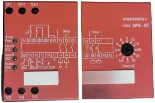
Figure 3.1: Front view of the Aoleaby XPS-AT Safety Relay, showing the detailed wiring diagram on the left panel and the time delay adjustment dial on the right panel. Key terminals such as B1, S11, S21, A1/A2, S12, S22, Y1-Y5, and output contacts (13, 23, 33, 14, 24, 34, 41, 57, 67, 42, 58, 68, PE, A2) are clearly labeled. The time dial allows setting delays from 0.5 to 30 seconds.
3.1. Wiring Connections
- Power Supply (A1/A2): Connect the main power supply to terminals A1 and A2. Ensure the voltage matches the relay's specifications.
- Inputs (S11, S12, S21, S22, B1): Connect safety devices such as emergency stop buttons, light curtains, or safety gates to the designated input terminals (e.g., S11, S12, S21, S22). The B1 terminal is typically used for reset or monitoring functions.
- Outputs (13, 14, 23, 24, 33, 34, 41, 42, 57, 58, 67, 68): Connect the controlled load or subsequent safety circuits to the output contacts. The diagram indicates both normally open (NO) and normally closed (NC) contacts.
- Auxiliary Outputs (Y1-Y5): These terminals provide additional signaling or monitoring capabilities.
- Protective Earth (PE): Ensure proper grounding by connecting the protective earth to the PE terminal.
3.2. Mounting
Mount the safety relay securely on a DIN rail or suitable panel within an enclosure to protect it from environmental factors and unauthorized access. Ensure adequate ventilation around the device.
4. Operating Instructions
Once properly installed and wired, the XPS-AT Safety Relay operates by continuously monitoring the connected safety circuits. Its primary function is to ensure that machinery or processes are safely shut down or prevented from starting if a hazardous condition is detected.
4.1. Time Delay Adjustment
The right panel of the relay features a rotary dial for adjusting the time delay, labeled "Time [s]". This allows for configurable delays in certain safety functions, typically for controlled stops or delayed activation.
- Use a small flat-head screwdriver to carefully turn the dial to the desired time setting.
- Available settings range from 0.5 seconds to 30 seconds.
- Refer to your system's safety requirements for the appropriate time delay setting.
4.2. Status Indicators
The relay may include LED indicators (e.g., "Fuse", "Input A S12", "Input B S22", "Output Stop") to provide visual feedback on its operational status and the state of connected inputs/outputs. Consult the specific model's documentation for detailed indicator meanings.
4.3. Reset Function
After a safety function has been triggered and the hazardous condition resolved, the relay typically requires a manual or automatic reset to restore normal operation. Refer to the wiring diagram for the specific reset input (e.g., B1 or a dedicated reset button connected to a specific input).
5. Maintenance
The Aoleaby XPS-AT Safety Relay is designed for long-term, reliable operation with minimal maintenance. However, periodic checks are recommended to ensure continued safety and performance.
- Visual Inspection: Regularly inspect the relay and its wiring for any signs of damage, loose connections, or overheating.
- Functionality Test: Periodically test the safety functions connected to the relay (e.g., activate emergency stop, open safety gate) to confirm the relay responds correctly.
- Cleaning: Keep the relay free from dust and debris. Use a soft, dry cloth for cleaning. Do not use solvents or abrasive cleaners.
- Firmware Updates: This device typically does not require firmware updates. If applicable for future models, follow manufacturer guidelines.
Always disconnect power before performing any maintenance or cleaning procedures.
6. Troubleshooting
If the safety relay is not functioning as expected, consider the following common issues and solutions:
| Problem | Possible Cause | Solution |
|---|---|---|
| Relay does not activate/reset |
|
|
| Unexpected shutdown |
|
|
| LED indicators not lit |
|
|
For issues not covered here, or if troubleshooting steps do not resolve the problem, please contact Aoleaby technical support.
7. Specifications
| Parameter | Value |
|---|---|
| Model Number | Aoleaby (XPS-AT) |
| ASIN | B0DF7LSZ31 |
| Package Dimensions | 1.18 x 0.79 x 0.39 inches |
| Item Weight | 2.2 pounds |
| Manufacturer | Aoleaby |
| Number of Pieces | 1 |
8. Warranty and Support
Specific warranty information for the Aoleaby XPS-AT Safety Relay is not provided in the product details. Please refer to the seller's return policy or contact the manufacturer, Aoleaby, directly for warranty details and technical support.
For technical assistance or inquiries, please contact your point of purchase or the manufacturer's customer service department.
Related Documents - XPS-AT
 |
Dell XPS 8930 Service Manual: Comprehensive Guide Detailed service manual for the Dell XPS 8930 desktop computer, covering component removal, replacement, system setup, and troubleshooting. |
 |
Newport XPS-D Universal High-Performance Motion Controller/Driver Start-Up Manual Comprehensive start-up manual for the Newport XPS-D Universal High-Performance Motion Controller/Driver. Covers system overview, specifications, setup, connectivity, programming, maintenance, and hardware details for advanced motion control applications. |
 |
Aideepen 40A Waterproof Automotive Relay (JD1912, JD1914, JD2912, JD2914) Technical specifications and features for Aideepen 12V/24V 40A waterproof automotive relays. Ideal for automotive, communication, and industrial control systems. |
 |
VEVOR Digital Phase Shifter XPS-2.5HP, XPS-5HP, XPS-7.5HP, XPS-10HP User Manual and Technical Specifications Comprehensive user manual and technical specifications for VEVOR Digital Phase Shifters, models XPS-2.5HP, XPS-5HP, XPS-7.5HP, and XPS-10HP. Includes safety instructions, operation guide, and troubleshooting. |
 |
VEVOR Digital Phase Shifter XPS Series User Manual User manual and technical specifications for VEVOR Digital Phase Shifter models XPS-2.5HP, XPS-5HP, XPS-7.5HP, and XPS-10HP, including safety precautions, operational steps, and troubleshooting guidance. |
 |
VEVOR Digital Phase Shifter User Manual This user manual provides detailed instructions and technical specifications for the VEVOR Digital Phase Shifter models XPS-2.5HP, XPS-5HP, XPS-7.5HP, and XPS-10HP. Learn about safety precautions, operation, and troubleshooting. |
Ask a question about this manual
Ask about setup, troubleshooting, compatibility, parts, safety, or missing instructions. Manuals+ will review the question and use this page’s manual context to help answer it.