1. Introduction
This manual provides essential instructions for the safe and efficient operation of your Nippon America Automatic Voltage Regulator, model ATVR-500. Please read this manual thoroughly before installation and use, and retain it for future reference. This device is designed to regulate voltage fluctuations, providing a stable power supply to connected appliances.
Safety Precautions
- Do not open the unit. Servicing should only be performed by qualified technicians.
- Ensure proper ventilation around the unit to prevent overheating.
- Do not expose the unit to moisture or extreme temperatures.
- Connect the unit to a properly grounded power outlet.
- Verify the input and output voltage settings match your requirements before connecting appliances.
- The total power consumption of connected appliances must not exceed the regulator's maximum capacity of 500 watts.
2. Product Overview
The ATVR-500 is an automatic voltage regulator designed to protect your electronic devices from voltage fluctuations. It features a CPU control circuit, delay function, and multiple protection mechanisms.
Key Features
- 500 Watts Capacity: Provides stable power for various appliances.
- Advanced CPU Control Circuit: Monitors input voltage and disconnects power if voltage exceeds 279V, reactivating when safe.
- 3-Minute Delay Function: Protects motors and compressors from frequent switching damage.
- Temperature Protection Circuit: Safeguards the transformer from overheating.
- High Output Voltage Protection: Protects appliances from voltage above 250V.
- Input and Output Voltage Display: Allows real-time monitoring of voltage levels.
- LED Indicators: Shows AC input voltage and delay mode status.
- Efficient Heat Dissipation: Large-area heat dissipation holes ensure stable operation.
- Convenient Handle: For easy portability.
Component Identification

Figure 2.1: Front view of the ATVR-500 Automatic Voltage Regulator. This image displays the overall design, including the front panel with meters and switches, and the carrying handle on top.

Figure 2.2: Close-up of the ATVR-500 front panel. This detailed view shows the input voltage meter, output voltage meter, power ON/OFF switch, LED indicators for power, time delay, protect, and input voltage ranges (80-140V, 140-260V), and delay settings (180s, 6s).

Figure 2.3: Rear panel of the ATVR-500. This image highlights the output sockets for AC 220V and AC 110V, the input power cord, a circuit breaker (press to reset), a temperature-activated fan, and a caution label regarding electric shock and servicing.
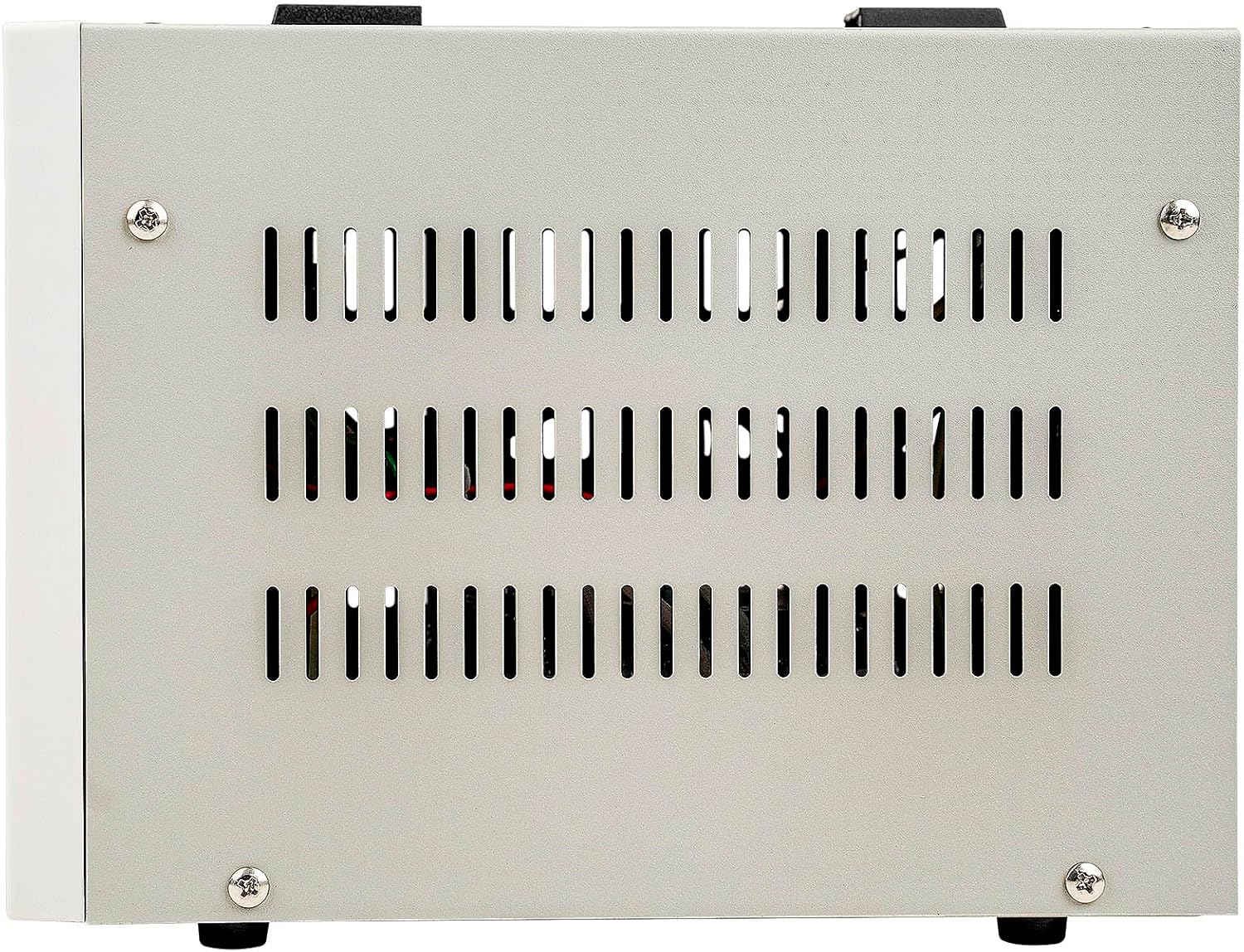
Figure 2.4: Side view of the ATVR-500, showing the ventilation grilles. These grilles are part of the efficient heat dissipation design, crucial for maintaining stable internal temperatures during operation.
3. Setup
3.1 Placement
- Place the ATVR-500 on a stable, flat surface.
- Ensure adequate space around the unit for proper ventilation. Do not block the heat dissipation holes on the sides and rear.
- Avoid placing the unit in direct sunlight, near heat sources, or in areas with high humidity or dust.
3.2 Connecting the Regulator
- Input Power: Connect the ATVR-500's integrated power cord to a suitable wall outlet. Ensure the wall outlet provides the correct input voltage (80-140V or 140-260V) as indicated on the unit.
- Output Voltage Selection: The unit provides both 110V and 220V output sockets. Identify the correct output socket for your appliance based on its voltage requirements.
- Connecting Appliances: Plug your electronic appliances into the appropriate output sockets on the rear panel of the ATVR-500. Ensure the total wattage of all connected devices does not exceed 500 watts.
4. Operation
4.1 Powering On/Off
- To power on the unit, press the red ON/OFF switch on the front panel to the 'ON' position.
- The "POWER ON" LED indicator will illuminate.
- To power off, press the switch to the 'OFF' position.
4.2 Monitoring Voltage
- The front panel features an Input Voltage meter and an Output Voltage meter. These displays show the real-time voltage levels.
- The LED indicators for "IN 80-140V" and "IN 140-260V" will light up to indicate the current input voltage range.
4.3 Delay Function
- Upon powering on, the unit initiates a 3-minute (180 seconds) delay. This is indicated by the "TIME DELAY" LED.
- This delay protects sensitive appliances, especially those with motors or compressors, from damage caused by immediate power restoration after an interruption.
- After the delay, power will be supplied to the output sockets.
- A shorter 6-second delay option is also available, typically for 220V output only, as indicated by the "DELAY (6s)" LED.
4.4 Protection Features
- Over-Voltage Protection: If the input voltage exceeds 279V or the output voltage exceeds 250V, the unit will automatically cut off power to protect connected devices. The "PROTECT" LED may illuminate.
- Temperature Protection: An internal circuit protects the transformer from overheating. If the internal temperature becomes too high, the unit will temporarily shut down.
- Circuit Breaker: The rear panel includes a resettable circuit breaker. If an overload occurs, the breaker will trip.
5. Maintenance
5.1 Cleaning
- Ensure the unit is powered off and unplugged before cleaning.
- Use a soft, dry cloth to wipe the exterior surfaces.
- Do not use liquid cleaners or abrasive materials.
- Keep ventilation openings clear of dust and debris.
5.2 Circuit Breaker Reset
- If the unit stops providing power due to an overload, the circuit breaker on the rear panel may have tripped.
- Disconnect all connected appliances.
- Press the circuit breaker button to reset it.
- Reconnect appliances one by one, ensuring the total load does not exceed 500 watts.
6. Troubleshooting
| Problem | Possible Cause | Solution |
|---|---|---|
| Unit does not power on. | No power from wall outlet; Power switch off; Tripped circuit breaker. | Check wall outlet with another device; Ensure power switch is ON; Reset circuit breaker on rear panel. |
| No output power after powering on. | Delay function active; Overload protection; High/Low voltage protection. | Wait for the 3-minute delay to complete; Reduce connected load and reset breaker; Check input voltage on display. |
| Output voltage is unstable. | Extreme input voltage fluctuations; Overloaded unit. | Ensure input voltage is within the specified range (80-140V or 140-260V); Reduce connected load. |
| Unit feels hot. | Blocked ventilation; Overloaded unit; High ambient temperature. | Ensure ventilation holes are clear; Reduce connected load; Move unit to a cooler environment. |
7. Specifications
| Feature | Detail |
|---|---|
| Model Number | ATVR-500 |
| Voltage Ampere (VA) | 500VA |
| Input Voltage | 80-140V / 140-260V |
| Output Voltage | 110V ±8% / 220V ±8% |
| Frequency | 50-60Hz |
| Delay Function | 3 minutes (180s) / 6 seconds (220V only) |
| Protection | Over-voltage, Over-temperature, Overload |
| Display | Input/Output Voltage Meters, LED Indicators |
| Item Weight | 10.8 pounds (4.9 kg) |
| Package Dimensions | 27.4 x 12 x 9.2 inches |
| Manufacturer | Nippon America |
| UPC | 784644411339 |
8. Warranty and Support
For warranty information and technical support, please refer to the warranty card included with your product or contact Nippon America customer service directly. Contact details can typically be found on the manufacturer's official website or product packaging.
Serial Number: 0524ATVR50000180