Introduction
This manual provides detailed instructions for the installation, operation, and maintenance of the BAISULI EAMT1-M1 Multifunction Time Delay Relay. Please read this manual thoroughly before use to ensure proper function and safety.
Safety Information
WARNING: Electrical shock hazard. Installation and maintenance should only be performed by qualified personnel. Disconnect power before installation or servicing.
- Ensure the supply voltage matches the relay's specifications (AC/DC 12V-240V).
- Do not exceed the maximum switching current of 16 Amps or maximum switching voltage of 250 Volts.
- Mount the device securely on a DIN rail.
- Protect the device from moisture, dust, and extreme temperatures.
Product Overview
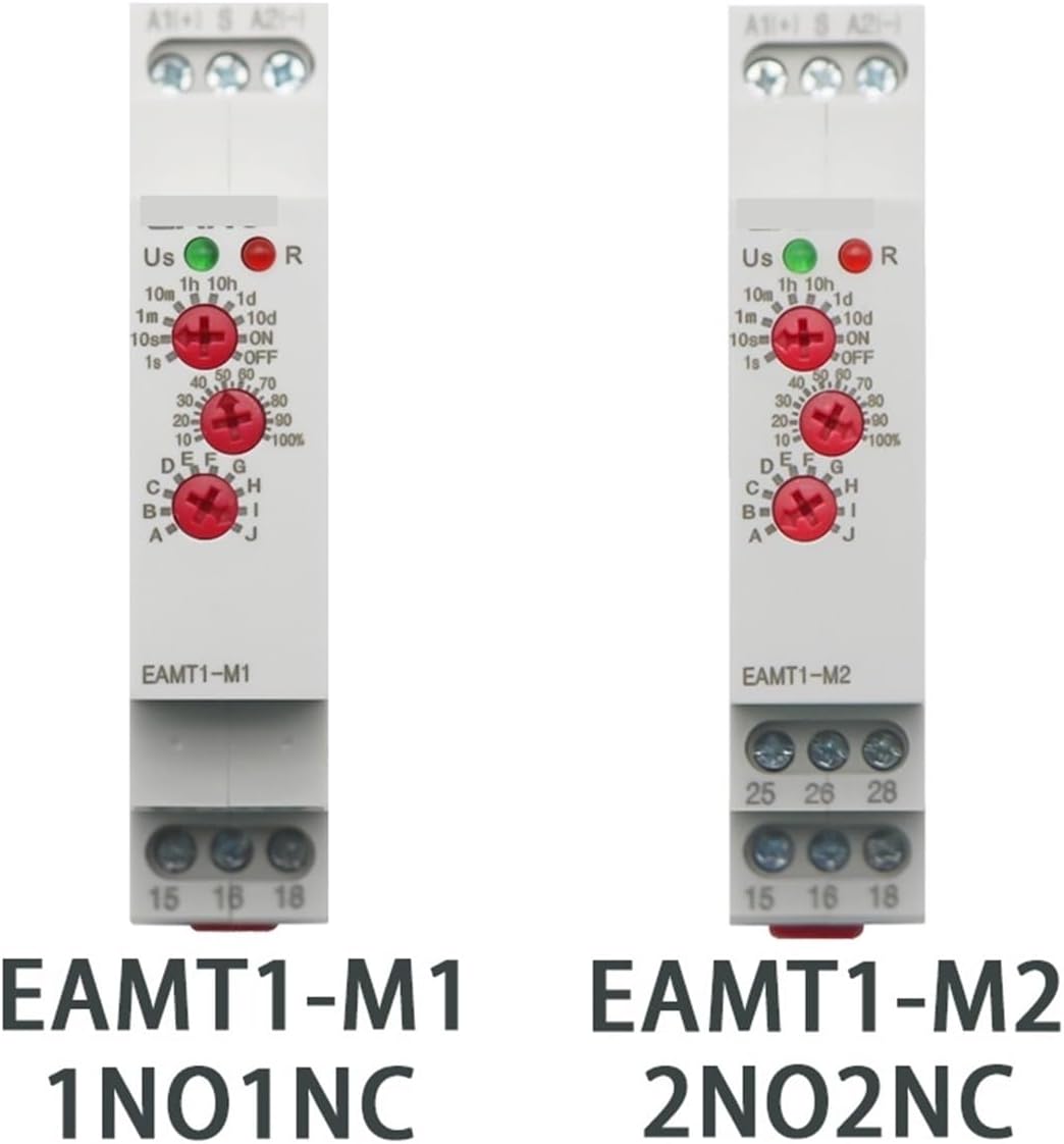
The BAISULI EAMT1-M1 is a versatile multifunction time delay relay designed for various industrial and home automation applications. It offers 10 selectable time functions and a wide time delay range from 0.1 seconds to 10 days.
Key Features:
- Wide operating voltage: AC/DC 12V-240V
- High contact rating: 16A / 250VAC
- 10 selectable time functions (A-J)
- Adjustable time range: 0.1 seconds to 10 days
- DIN rail mountable
- LED indicators for power (Us) and relay status (R)
Specifications
| Parameter | Value |
|---|---|
| Model | EAMT1-M1 |
| Operating Voltage | AC/DC 12V-240V |
| Current Rating | 16 Amps |
| Contact Current Rating | 16 Amps |
| Maximum Switching Current | 16 Amps |
| Maximum Switching Voltage | 250 Volts |
| Time Delay Range | 0.1 seconds - 10 days |
| Number of Functions | 10 (A-J) |
| Mounting Type | DIN Rail |
| Item Weight | 200 Grams |

Setup
1. Mounting
The EAMT1-M1 relay is designed for DIN rail mounting. Securely attach the relay to a standard 35mm DIN rail in an appropriate enclosure.

2. Wiring
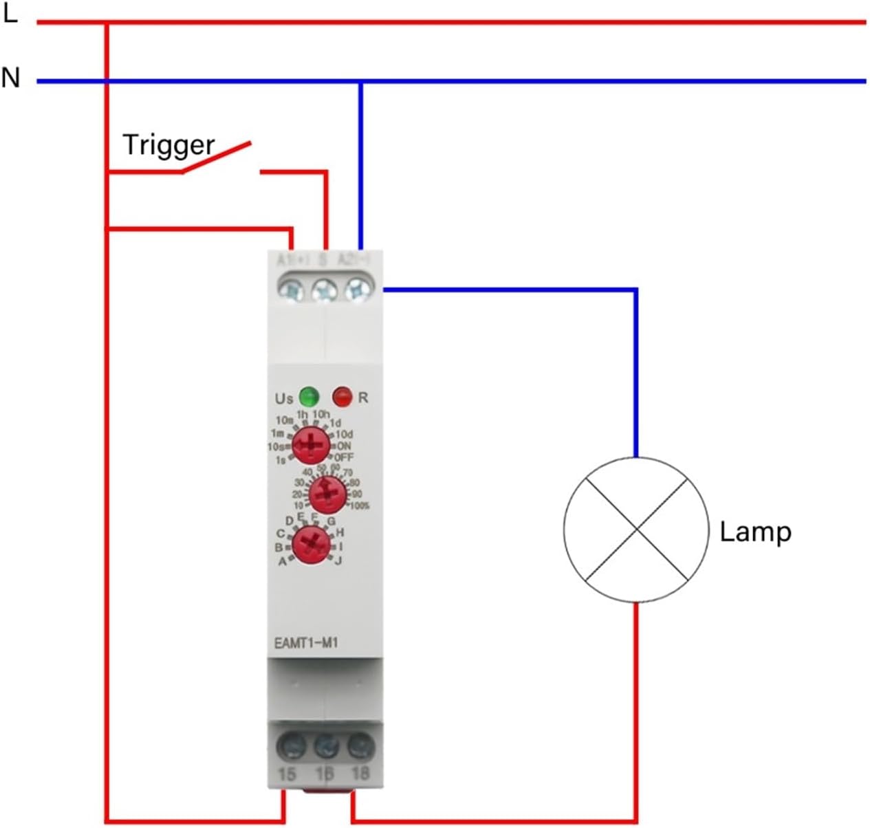
Refer to the wiring diagram below for correct connections. Ensure all connections are secure and comply with local electrical codes.
- A1, A2: Supply Voltage (AC/DC 12V-240V). Connect the power supply to these terminals.
- S: Trigger Terminal. This terminal is used for specific functions (e.g., Off Delay, Single Shot).
- 15: Common contact for the output relay.
- 16: Normally Closed (NC) contact.
- 18: Normally Open (NO) contact.
Operating Instructions
The EAMT1-M1 relay features three rotary switches on the front panel for function selection, time range, and time adjustment.
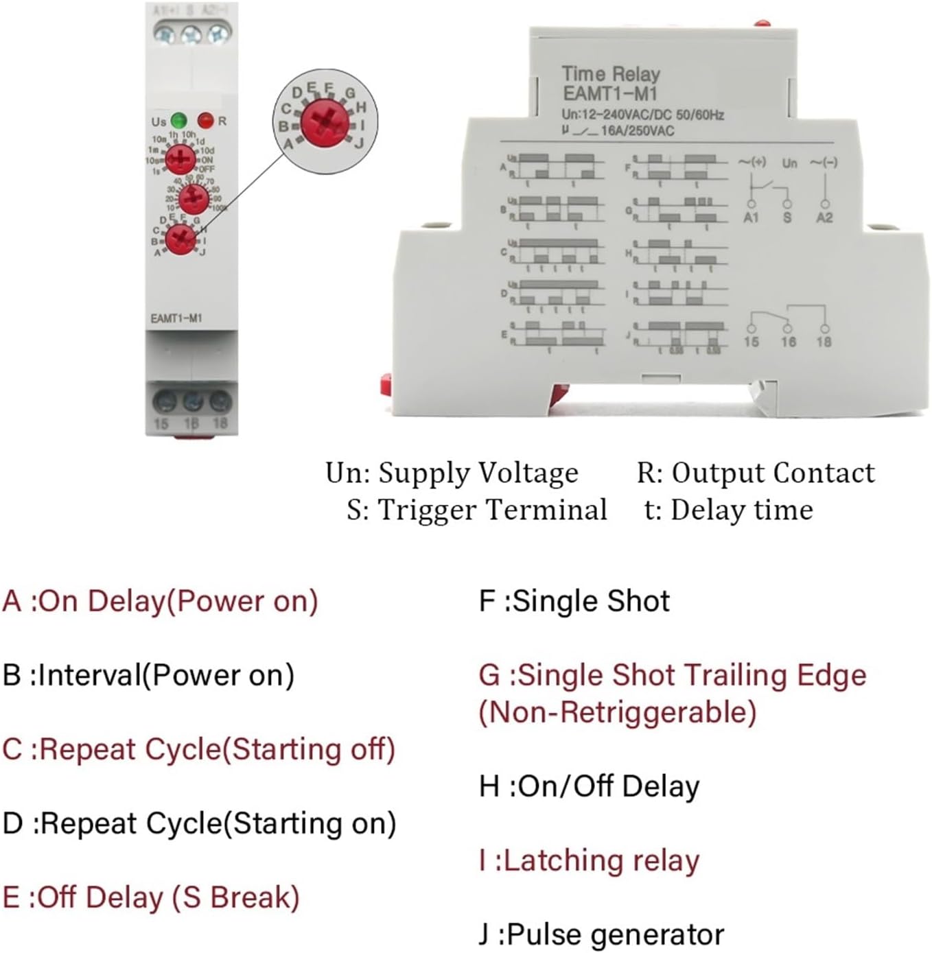
1. Function Selection
Use the middle rotary switch (labeled A-J) to select one of the 10 available time functions:
- A: On Delay (Power on) - The relay energizes after a set delay once power is applied.
- B: Interval (Power on) - The relay energizes immediately upon power application and de-energizes after a set delay.
- C: Repeat Cycle (Starting off) - The relay cycles between OFF and ON states, starting with OFF, with set delays for each state.
- D: Repeat Cycle (Starting on) - The relay cycles between ON and OFF states, starting with ON, with set delays for each state.
- E: Off Delay (S Break) - The relay de-energizes after a set delay once the trigger (S) is removed.
- F: Single Shot - A brief pulse on the trigger (S) causes the relay to energize for a set delay.
- G: Single Shot Trailing Edge (Non-Retriggerable) - The relay energizes for a set delay upon the falling edge of the trigger (S). Subsequent triggers during the delay are ignored.
- H: On/Off Delay - A combination of on-delay and off-delay functions.
- I: Latching relay - The relay changes state with each pulse on the trigger (S).
- J: Pulse generator - Generates continuous pulses with a set ON and OFF time.
2. Time Range Selection
Use the top rotary switch to select the desired time range:
- 10s (0.1s - 10s)
- 1m (0.1m - 1m)
- 10m (0.1m - 10m)
- 1h (0.1h - 1h)
- 10h (0.1h - 10h)
- 1d (0.1d - 1d)
- 10d (0.1d - 10d)
3. Time Adjustment
Use the bottom rotary switch (0-100%) to fine-tune the delay time within the selected range. For example, if the range is 10s and the dial is set to 50%, the delay will be 5 seconds.
4. LED Indicators
- Us (Green LED): Illuminates when power is supplied to the relay.
- R (Red LED): Illuminates when the output relay is energized.
Maintenance
The BAISULI EAMT1-M1 time delay relay is designed for maintenance-free operation under normal conditions.
- Periodically inspect wiring connections for tightness and signs of wear.
- Keep the device clean and free from dust and debris.
- Ensure adequate ventilation around the device to prevent overheating.
- Do not attempt to open or repair the device. Refer to qualified service personnel if a malfunction occurs.
Troubleshooting
If the relay is not functioning as expected, consider the following:
| Problem | Possible Cause | Solution |
|---|---|---|
| Green "Us" LED is off. | No power supply or incorrect wiring to A1/A2. | Check power supply voltage and wiring connections. Ensure voltage is within AC/DC 12V-240V. |
| Red "R" LED does not illuminate or relay does not switch. | Incorrect function selection, time setting, or trigger input (if applicable). Overload on output contacts. | Verify the selected function (A-J) and time range/adjustment. Check trigger input (S) if the function requires it. Ensure load current does not exceed 16A. |
| Relay operates erratically. | Unstable power supply, electrical interference, or faulty unit. | Ensure stable power. Check for sources of electrical noise. If problem persists, the unit may be faulty. |
Warranty and Support
For warranty information and technical support, please contact BAISULI customer service through your purchase platform or refer to the documentation provided with your product at the time of purchase.
Return Policy: This product typically comes with a 30-day return/replacement policy. Please check your purchase details for specific terms.