1. Product Overview
The PerGar Network Cable Tester (Model PerGar2mnupzwx1i) is a versatile tool designed for testing various types of cables, including network (Ethernet), telephone, and electrical wires. It is suitable for weak current equipment below 65V, such as switches and routers. This device helps identify common cable issues like open circuits, short circuits, miswires, and reverse connections, ensuring the integrity and stability of your network and communication lines.
Key features include:
- Versatile Compatibility: Tests Ethernet LAN wires, electrical wires, and speaker wires when connected to the clip.
- Enhanced Audio Functionality: Includes earphones and a volume knob for clear information retrieval in noisy environments.
- Reliable Physical Connection Testing: Accurately detects open circuits, short connections, miswires, and reverse connections.
- Easy and Convenient Operation: Features adjustable sensitivity and simple controls for efficient line finding and measurement.
- Wide Application Range: Offers two independent line hunting and line measuring modes to suit different testing requirements.
2. Package Contents
Please verify that all items listed below are present in your package:
- 1 x PerGar Network Cable Tester (Emitter Unit)
- 1 x Receiver Unit (Wire Tracker)
- 2 x Test Cables (RJ11 and RJ45)
- 1 x Test Clip (Alligator Clip Cable)
- 1 x Earphone
- 1 x Instruction Manual (this document)
- 1 x Storage Bag

Image: The PerGar Network Cable Tester includes both the emitter and receiver units, along with essential accessories like test cables.
3. Specifications
| Model Number | PerGar2mnupzwx1i |
| ASIN | B0DF5HNYXS |
| Manufacturer | PerGar |
| Power Source | Detector: 9V 6F22 Battery x 1 (Not Included) Receiver: 9V 6F22 Battery x 1 (Not Included) |
| Item Weight | 11.1 ounces (approx. 315 grams) |
| Package Dimensions | 9.45 x 5.91 x 1.97 inches (approx. 24 x 15 x 5 cm) |
| Application Scope | Weak current equipment below 65V (e.g., switches, routers) |
4. Setup
4.1 Battery Installation
Both the Emitter and Receiver units require a 9V 6F22 battery each (not included). To install:
- Locate the battery compartment cover on the back of both the Emitter and Receiver units.
- Slide or unclip the cover to open the compartment.
- Insert a 9V 6F22 battery, ensuring correct polarity (+/-).
- Replace the battery compartment cover securely.
Note: Always use fresh batteries for optimal performance. Remove batteries if the device will not be used for an extended period.
4.2 Connecting Test Cables
Depending on the type of cable you are testing, select the appropriate test cable (RJ11 for telephone, RJ45 for network) or the alligator clip cable.
- For Network (RJ45) Cables: Connect one end of the RJ45 test cable to the RJ45 port on the Emitter unit.
- For Telephone (RJ11) Cables: Connect one end of the RJ11 test cable to the RJ11 port on the Emitter unit.
- For Electrical/Speaker Wires (using clip): Connect the alligator clip cable to the appropriate port on the Emitter unit, then attach the clips to the wires to be tested.

Image: The emitter and receiver units feature RJ45 and RJ11 ports for connecting various cable types.
5. Operating Instructions
5.1 Basic Continuity Test (Cable Scan & Test Device)
This function is used to check the basic continuity and wiring sequence of network and telephone cables.
- Connect the cable to be tested to the appropriate port (RJ45 or RJ11) on the Emitter unit.
- If testing a patch cable, connect the other end of the cable to the corresponding port on the Receiver unit. If testing an installed cable, the receiver is not used for this specific test, but rather for line hunting.
- On the Emitter unit, slide the function switch to the "SCAN" or "TEST" position.
- Observe the LED indicators on both the Emitter and Receiver (if connected). The LEDs will light up sequentially, indicating the wiring order.
- Any discrepancies (e.g., LEDs not lighting up, lighting up out of sequence, or short circuit indication) point to a wiring fault.

Image: The emitter unit features LED indicators for each wire, allowing for visual inspection of cable continuity and wiring sequence.
5.2 Line Hunting (Wire Tracking)
This function helps locate a specific cable among a bundle of cables or trace a cable's path.
- Connect the cable to be traced to the appropriate port on the Emitter unit.
- Turn on the Emitter unit and select the "SCAN" mode.
- Turn on the Receiver unit by pressing the "POWER" button.
- Adjust the sensitivity knob on the Receiver unit to an appropriate level.
- Move the tip of the Receiver unit along the cables. When the Receiver is near the target cable, it will emit an audible tone. The tone will be strongest when directly over the correct cable.
- Use the included earphones to reduce noise disturbance and improve detection accuracy, especially in noisy environments.

Image: The emitter and receiver units are used together for efficient line hunting, even in complex wiring environments like server racks.
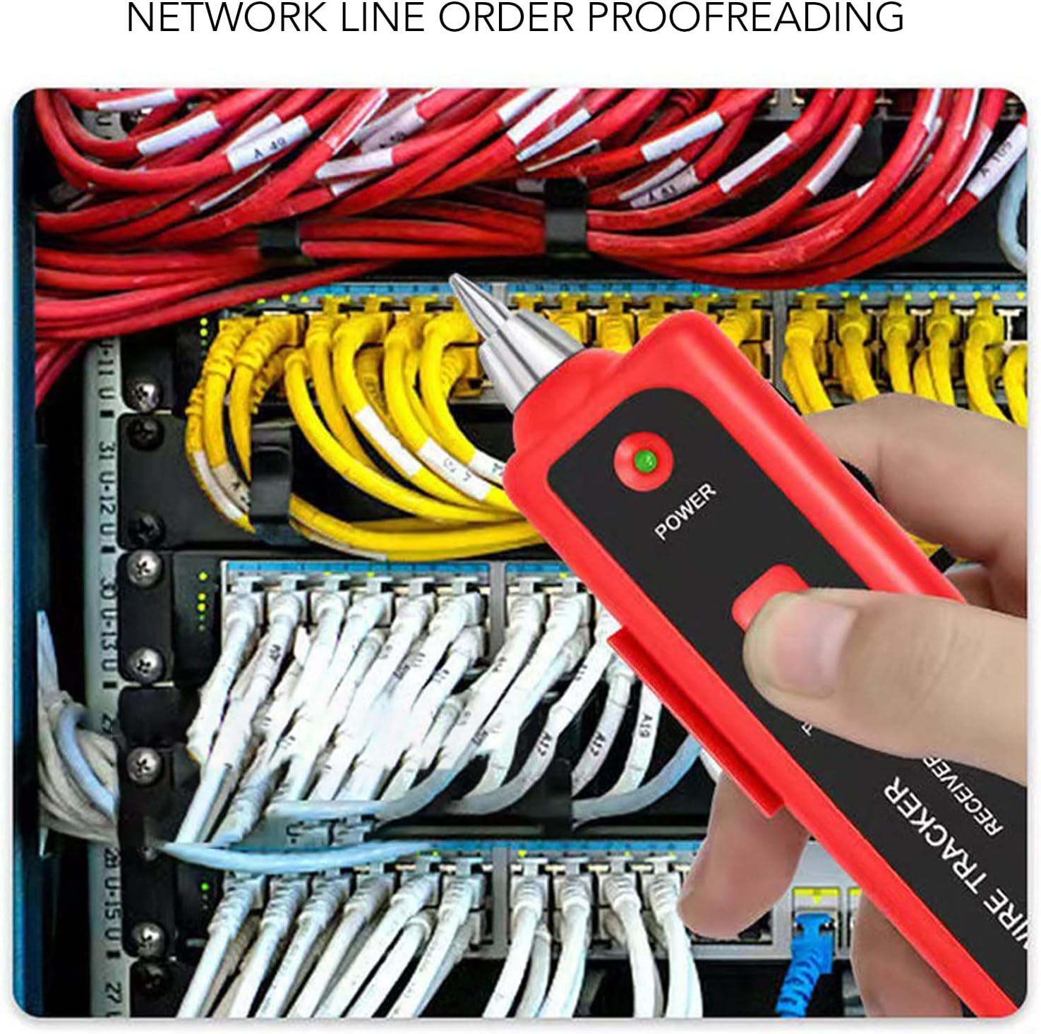
Image: The receiver unit can be used to identify specific network lines connected to a switch, aiding in network line order proofreading.
5.3 Lighting Function
The Receiver unit is equipped with a built-in LED light to assist in working in dimly lit areas.
- Press the dedicated light button (if available) or activate it via the power switch on the Receiver unit.
- The LED light at the tip of the receiver will illuminate, providing visibility for inspecting cables and ports.

Image: The receiver unit features a lighting function at its tip, useful for illuminating dark work areas.
6. Maintenance
- Cleaning: Wipe the device with a soft, dry cloth. Do not use abrasive cleaners or solvents.
- Storage: Store the cable tester in its provided storage bag in a cool, dry place, away from direct sunlight and extreme temperatures.
- Battery Care: Remove batteries if the device is not going to be used for an extended period to prevent leakage and damage. Dispose of used batteries responsibly.
- Avoid Moisture: Do not expose the device to water or high humidity.
7. Troubleshooting
| Problem | Possible Cause | Solution |
|---|---|---|
| Device does not power on. |
|
|
| No tone during line hunting. |
|
|
| LEDs on Emitter/Receiver do not light up correctly during continuity test. |
|
|
8. Warranty and Support
Information regarding product warranty and customer support was not available in the provided product data. Please refer to the product packaging or contact the retailer/manufacturer directly for details on warranty coverage and support services.
Manufacturer: PerGar