1. Introduction
The GHSOGEOM HS-617A is a digital instrument designed to control circulating pumps in solar hot water systems based on temperature differences. It features a digital display for real-time temperature monitoring and adjustable settings for precise control of water circulation, optimizing energy efficiency.
2. Product Overview
The HS-617A controller monitors two temperature points (A and B) and activates an output based on their difference. This allows for efficient management of solar hot water systems, ensuring the circulating pump operates only when beneficial.
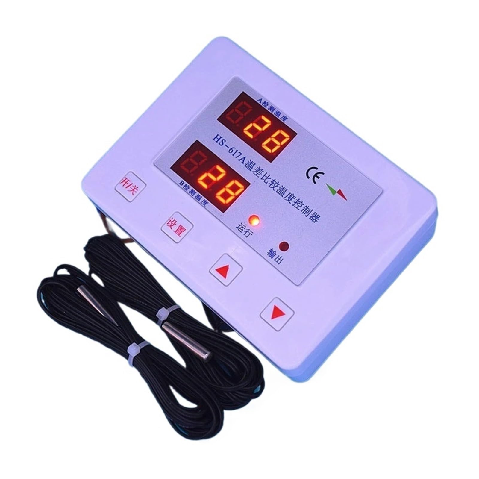
Figure 2.1: The GHSOGEOM HS-617A controller with its two temperature probes. The device features a white casing, two digital displays for temperature readings, and control buttons.

Figure 2.2: Close-up view of the HS-617A controller's front panel. It shows two red digital displays labeled 'A 检测温度' (A Detection Temperature) and 'B 检测温度' (B Detection Temperature), along with indicator lights for '运行' (Run) and '输出' (Output). Control buttons include '开/关' (On/Off), '设置' (Set), and up/down arrows.

Figure 2.3: The back panel of the HS-617A controller, illustrating the wiring terminals. Labels indicate connections for 'Low temperature probe', 'High temperature probe', 'output device', and 'power input'. Mounting holes are also visible, with a distance of 60mm between them.
3. Specifications
- Product Model: HS-617A
- Control Object: 1 electrical appliance (e.g., circulating pump)
- Voltage Range: 85-250VAC
- Maximum Power: 2000W
- Temperature Detection: Bidirectional (High Temperature - Atemp, Low Temperature - Btemp)
- Detection Range: 1°C to 110°C
- Temperature Difference Adjustment Range:
- Upper Limit Temperature Difference: 3°C to 40°C (Factory Default: 5°C)
- Lower Limit Temperature Difference: 1°C to 35°C (Factory Default: 2°C)
- Temperature Control Prerequisite: A > 30°C (Adjustable range: 1°C to 110°C, factory default 30°C)
- Package Dimensions: 1.18 x 0.79 x 0.39 inches
- Item Weight: 1.76 ounces (50 Grams)
4. Setup
4.1 Wiring Instructions
Refer to Figure 2.3 for the wiring diagram on the back panel of the controller.
- Probe Connection: Connect the high-temperature probe to the terminals labeled 'High temperature probe' and the low-temperature probe to the terminals labeled 'Low temperature probe'. Ensure correct polarity if specified by the probes.
- Output Device Connection: Connect your circulating pump or other controlled electrical appliance to the terminals labeled 'output device'. Ensure the appliance's power requirements do not exceed 2000W.
- Power Input: Connect the 85-250VAC power supply to the terminals labeled 'power input'. Ensure all connections are secure before applying power.
4.2 Probe Installation
Install the high-temperature probe (A) in the location where the solar collector's hot water is measured (e.g., solar panel outlet). Install the low-temperature probe (B) in the location where the water in the storage tank is measured. Ensure probes are securely placed and have good thermal contact with the water.
5. Operating Instructions
5.1 Power-On Sequence
Upon applying power, the digital displays will illuminate fully, and all indicator lights will turn on for approximately 2 seconds. The buzzer will sound twice, and the relay will cycle twice, indicating a successful power-on self-test.
5.2 Standby Display
After the initial power-on display, the controller enters standby mode. The Atemp and Btemp display windows will show the currently detected temperatures from their respective probes.
5.3 Temperature Control Operation Display
- When the temperature control function is active, the 'Run' indicator light will be illuminated. When the function is inactive, the 'Run' indicator light will be off.
- When the output (e.g., pump) is activated, the 'A' indicator light will be on. When the output is off, the 'A' indicator light will be off.
5.4 Basic Functions and Parameters
- Temperature Control Prerequisite: The controller will only begin temperature difference comparison operation if the temperature of probe A is greater than the set prerequisite temperature. The factory default is 30°C, but this value can be adjusted between 1°C and 110°C using the 'Set' button and arrow keys.
- Heating Mode: In heating mode, the output is activated when the temperature of A is greater than the upper limit of the temperature difference between A and B. The output remains active until the temperature difference falls below the lower limit.
5.5 Adjusting Settings
To adjust parameters such as the temperature difference limits or the prerequisite temperature, press the '设置' (Set) button. Use the up and down arrow buttons to change the values. Press '设置' again to confirm and cycle through settings, or wait for the display to return to standby mode to save changes automatically.
6. Maintenance
To ensure optimal performance and longevity of your HS-617A controller, follow these maintenance guidelines:
- Cleaning: Periodically wipe the controller's exterior with a soft, dry cloth. Do not use abrasive cleaners or solvents.
- Connections: Regularly inspect all wiring connections to ensure they are secure and free from corrosion. Loose connections can lead to erratic operation or damage.
- Probe Condition: Check the temperature probes for any signs of damage or wear. Ensure they are properly seated and making good thermal contact.
- Environment: Ensure the controller is installed in a dry environment, away from direct sunlight, extreme temperatures, and excessive humidity.
7. Troubleshooting
This section provides solutions to common issues you might encounter with the HS-617A controller.
- Controller does not power on:
- Check the power input connections for secure contact.
- Verify that the power supply is within the 85-250VAC range.
- Ensure the power source is active.
- Displays show '---' or incorrect temperature:
- Check the temperature probe connections. Ensure they are securely plugged in and not damaged.
- Verify that the probes are correctly installed in their respective temperature sensing locations.
- If a probe is faulty, it may need replacement.
- Output (pump) does not activate:
- Check if the 'Run' indicator light is on, indicating the control function is active.
- Verify that the temperature of probe A meets the prerequisite (A > 30°C by default).
- Ensure the temperature difference between A and B is greater than the set upper limit.
- Check the wiring to the output device (pump) for secure connections.
- Confirm the output device itself is functional.
- Output (pump) does not turn off:
- Ensure the temperature difference between A and B has fallen below the set lower limit.
- Check for any short circuits in the output wiring.