1. Introduction
This manual provides essential information for the safe and effective installation, operation, and maintenance of the uxcell V-156-1C25 Micro Limit Switch. This precision component is designed to monitor the position of moving parts in various mechanical systems and can be integrated into AC/DC control circuits for terminal limit protection.
Please read this manual thoroughly before using the product to ensure proper function and to prevent potential hazards.

Figure 1: Package containing six uxcell V-156-1C25 Micro Limit Switches.
2. Product Specifications
The uxcell V-156-1C25 Micro Limit Switch features a robust design suitable for various industrial and home applications. Key specifications are detailed below:
| Specification | Value |
|---|---|
| Model | V-156-1C25 |
| Contact Type | 1 Normally Open (NO) + 1 Normally Closed (NC) |
| Current Voltage Rating | 15A 125/250VAC |
| Protection Degree | IP40 (Dust ingress protected, protected against water spray) |
| Overall Size (L*W*H) | 28mm x 16mm x 10mm (1.1" x 0.63" x 0.39") |
| Pin Length | 9mm (0.35") |
| Mounting Type | Surface Mount |
| Unit Count | 6 per package |
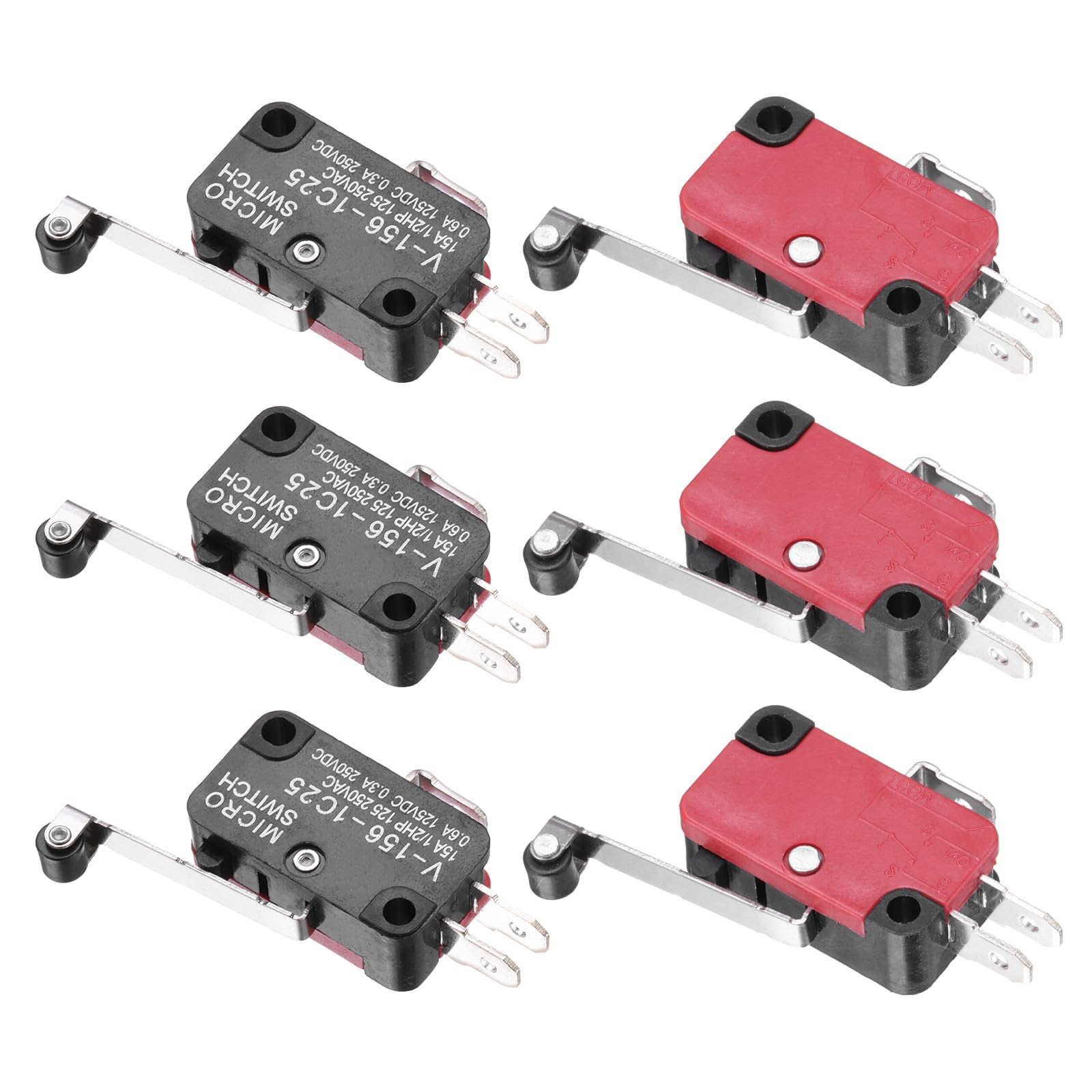
Figure 2: Detailed dimensions and contact configuration of the micro limit switch.
3. Safety Information
WARNING: Electrical components can cause injury or death. Always disconnect power before installation, maintenance, or troubleshooting. Installation should only be performed by qualified personnel.
- Ensure the power supply matches the switch's voltage and current ratings.
- Avoid exposing the switch to conditions beyond its IP40 rating (e.g., direct water immersion).
- Verify all connections are secure to prevent short circuits or loose contacts.
- Do not modify the switch or its components.
4. Setup and Installation
The V-156-1C25 micro limit switch is designed for surface mounting and integration into control circuits.
4.1. Mounting
- Identify a suitable mounting location where the switch's lever can be actuated by the moving part it is intended to monitor.
- Secure the switch using appropriate fasteners through its mounting holes. Ensure it is firmly attached to prevent movement during operation.
- Adjust the position of the switch or the actuator arm to ensure reliable contact and release with the moving part.
4.2. Wiring
The switch features 1 Normally Open (NO) and 1 Normally Closed (NC) contact, along with a Common (COM) terminal. Refer to the markings on the switch for correct terminal identification.
- COM (Common): This is the shared terminal for both NO and NC contacts.
- NO (Normally Open): This contact is open (no current flow) when the switch is in its unactuated (rest) position and closes (allows current flow) when the switch is actuated.
- NC (Normally Closed): This contact is closed (allows current flow) when the switch is in its unactuated (rest) position and opens (stops current flow) when the switch is actuated.
Connect the switch into your AC or DC control circuit according to your application's requirements. Always ensure power is disconnected before making any wiring connections.

Figure 3: Front view of the micro limit switch, highlighting the lever and electrical terminals.
5. Operating Principles
The uxcell V-156-1C25 micro limit switch operates by detecting the presence or absence of a mechanical object. When the lever arm is actuated by a moving part, the internal contacts switch their state:
- The Normally Open (NO) contact closes.
- The Normally Closed (NC) contact opens.
This change in contact state can be used to trigger or stop a process, activate an indicator, or provide feedback to a control system. The switch is designed for high precision and reliable operation over many cycles.
6. Maintenance
The V-156-1C25 micro limit switch is designed for durability and requires minimal maintenance. However, periodic checks can extend its lifespan and ensure reliable operation.
- Inspection: Regularly inspect the switch for any physical damage, loose connections, or excessive wear on the lever arm.
- Cleaning: Due to its IP40 rating, the switch is protected against dust. If dust accumulation is observed, gently clean the exterior with a dry, soft cloth. Avoid using liquids or abrasive cleaners.
- Actuation Check: Periodically verify that the switch actuates smoothly and consistently when triggered by the moving part.
- Wiring Integrity: Ensure all wiring connections remain secure and free from corrosion.
Always disconnect power before performing any maintenance or inspection.
7. Troubleshooting
If the micro limit switch is not functioning as expected, consider the following troubleshooting steps:
| Problem | Possible Cause | Solution |
|---|---|---|
| Switch does not actuate |
|
|
| No electrical signal change |
|
|
| Intermittent operation |
|
|
If problems persist after attempting these solutions, contact uxcell customer support or consult a qualified electrician.
8. Warranty and Support
For warranty information and technical support regarding your uxcell V-156-1C25 Micro Limit Switch, please refer to the official uxcell website or contact their customer service directly. Keep your purchase receipt for warranty claims.
Contact Information:
- Brand: uxcell
- Website: Visit the uxcell Store on Amazon
- Model Number: V-156-1C25
- Part Number: a24062900ux0690