1. Introduction
This manual provides detailed instructions for the installation, operation, and maintenance of the ETERMETA 4021-732 Pilot Assembly. This pilot assembly is designed as a replacement part for various natural gas fireplaces from Heatilator, Quadrafire, and Heat-N-Glo.
The 4021-732 pilot assembly is specifically for natural gas (NG) applications and is intended for standing pilot units only. It is not compatible with SIT valves.

Figure 1: A complete view of the ETERMETA 4021-732 Pilot Assembly, showing all components including the pilot burner, thermocouple, thermopile, and electrode with their respective tubing and wiring.
2. Package Contents and Components
The ETERMETA 4021-732 Pilot Assembly package includes the following components:
- 36" Thermopile
- 24" Pilot Tube
- 24" Electrode
- 24" Thermocouple

Figure 2: Close-up image highlighting the individual components of the pilot assembly: the thermopile, pilot burner, thermocouple, and electrode, clearly labeled for identification.

Figure 3: Detailed close-up images of the thermocouple tip, pilot tube connection, thermopile connection, and electrical spade connectors of the 4021-732 pilot assembly.
3. Compatibility
The ETERMETA 4021-732 Pilot Assembly is compatible with the following fireplace models. This assembly replaces part numbers 4021-732 and HHT part number 25660.
Heatilator Fireplaces Models:
- CD4236R & CD4236LR - Pre serial # GA1563745
- CD4842R & CD4842LR - Pre serial # GA1563745
- CGC150 & CGC150L - After date code 39/95
- G141 & G141L, G270M & G270LM
- GB4336 & GB4336L, GB4942 & GB4942L
- GBCL36 - Pre serial # GA1549727
- GBCR36 - Pre serial # GA1549727
Quadrafire Fireplaces Models:
- DV750 (POST SN 3196)
- DV425, DV425L
- SAPPHIRE 50 (DV750)
- DV-750, DV-450, DV-425, DV400S, DV-400, DV400, DV400L
- Twilight II-B
- DV750 (PRE SN 3096)
Heat-N-Glo Fireplace Models:
- R-CAST
Always double-check your fireplace model number before ordering or installing to ensure proper compatibility.
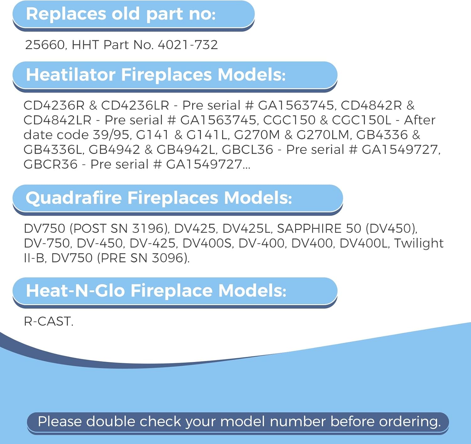
Figure 4: A list of compatible Heatilator, Quadrafire, and Heat-N-Glo fireplace models for the 4021-732 pilot assembly, along with cross-reference part numbers.
4. Safety Information
WARNING: Improper installation, adjustment, alteration, service, or maintenance can cause injury or property damage. Read the installation, operating, and maintenance instructions thoroughly before installing or servicing this equipment.
- This 4021-732 pilot assembly is designed for natural gas (NG) only. Do not attempt to use it with propane (LP) gas.
- This assembly is for standing pilot units only and is not compatible with SIT valves.
- Before performing any work on your fireplace, ensure the gas supply valve is completely turned off.
- Allow the fireplace to cool completely before attempting any replacement or maintenance procedures.
- If you are unsure about any step, consult a qualified service technician.
- Always check for gas leaks after any gas line work using a non-corrosive leak detection solution.

Figure 5: Image detailing the 4021-732 pilot assembly, emphasizing its exclusive use with natural gas and standing pilot units, not SIT valves.
5. Installation Instructions
Follow these steps carefully to install the ETERMETA 4021-732 Pilot Assembly. Ensure all safety precautions are observed before beginning.
- Step 1: Locate Gas Supply Valve. Find the gas supply valve, typically located behind the blinds or below the glass opening. It may be red or blue.
- Step 2: Open Gas Valve. Pivot the valve handle to be parallel with the gas line to open it.
- Step 3: Locate Pilot Assembly. Identify the pilot assembly with the spark igniter, usually situated behind and under the logs in the firebox, often in the bottom center.
- Step 4: Locate Igniter Button. Find the red or black igniter button. Press the igniter and confirm that a spark is visible in the pilot area.
- Step 5: Turn Control Knob. Locate the black or green valve control knob (marked with "ON", "OFF", and "PILOT"). Push it in and turn it counterclockwise until the word "PILOT" is at the 6 o'clock position.
- Step 6: Press and Hold Valve Knob. Press and hold the valve knob in the "PILOT" position. It should be pressed in about 1/4 inch. Repeatedly press the red piezo button (once per second) until the pilot ignites. After ignition, continue to press and hold the valve knob for 30 seconds, then slowly release.
- Step 7: Verify Pilot Light. If the pilot light goes out, repeat the process from Step 5. If the pilot light remains on, press the valve knob down slightly and turn it counterclockwise until the word "ON" is in the 6 o'clock position.
- Step 8: Finalize Installation. Finally, turn the unit's on/off switch (or wall switch or remote control) to the 'on' position to begin ignition. Before replacing the front, make sure the glass is securely clamped at all points.

Figure 6: An illustrated guide outlining the eight steps for installing the 4021-732 pilot assembly.
6. Operation
Once the pilot assembly is correctly installed and the pilot light is established (as per installation steps 5-7), the fireplace can be operated normally. To ignite the main burner, ensure the control knob is in the "ON" position and use the fireplace's main power switch or remote control.
To turn off the fireplace, turn the control knob to the "OFF" position and/or use the main power switch. If the pilot light needs to be extinguished for extended periods or maintenance, turn the control knob to the "OFF" position and ensure the gas supply valve is closed.
7. Maintenance
Regular maintenance ensures the longevity and safe operation of your pilot assembly and fireplace.
- Annual Inspection: It is recommended to have your fireplace and pilot assembly inspected annually by a qualified service technician.
- Cleaning: Periodically inspect the pilot burner and surrounding area for dust, lint, or debris. Gently clean with a soft brush or compressed air if necessary. Ensure the pilot flame is clear and strong.
- Flame Appearance: The pilot flame should be blue with a small yellow tip, enveloping the thermocouple and thermopile tips. If the flame is weak, yellow, or lifts off the pilot burner, it may indicate a problem requiring professional service.
- Component Check: Visually inspect the thermocouple, thermopile, and electrode for any signs of damage, corrosion, or wear. Replace components if they appear faulty.
IMPORTANT: Always turn off the gas supply and allow the fireplace to cool completely before performing any maintenance.
8. Troubleshooting
This section addresses common issues you might encounter with your pilot assembly.
Pilot Light Does Not Ignite:
- No Gas Supply: Ensure the main gas supply valve to the fireplace is fully open.
- Igniter Issue: Check if the igniter produces a spark. If not, the igniter or electrode may need replacement.
- Air in Line: If the gas line has been off, it may take several attempts to purge air from the line. Hold the pilot knob longer.
- Blocked Pilot Orifice: A clogged pilot orifice can prevent gas flow. This requires professional cleaning or replacement.
Pilot Light Ignites but Goes Out When Knob is Released:
- Insufficient Hold Time: Ensure you hold the pilot knob in for the recommended 30 seconds after ignition to allow the thermocouple/thermopile to heat up.
- Thermocouple/Thermopile Issue: The thermocouple or thermopile may be faulty, dirty, or not properly positioned in the pilot flame. It needs to generate enough voltage to keep the gas valve open. Inspect its position and condition. Replacement may be necessary.
- Weak Pilot Flame: A weak pilot flame may not adequately heat the thermocouple/thermopile. Check for blockages or adjustments.
Main Burner Does Not Ignite:
- Pilot Light Not On: The main burner will not ignite if the pilot light is not established.
- Control Knob Position: Ensure the control knob is fully in the "ON" position.
- Thermostat/Switch Issue: Check the fireplace's main power switch, wall switch, or remote control for proper function.
If these troubleshooting steps do not resolve the issue, contact a qualified service technician for assistance.
9. Specifications
| Model Number | 4021-732 |
| Manufacturer | ETERMETA |
| Gas Type | Natural Gas (NG) |
| Compatibility | Standing Pilot Units (Not for SIT valves) |
| Thermopile Length | 36 inches |
| Pilot Tube Length | 24 inches |
| Electrode Length | 24 inches |
| Thermocouple Length | 24 inches |
| Item Weight | 7 ounces |
| Package Dimensions | 5.55 x 5.35 x 1.38 inches |
10. Warranty and Support
For information regarding product warranty or technical support, please refer to the product packaging or contact ETERMETA customer service directly. Keep your purchase receipt for warranty claims.