1. Introduction
This manual provides essential information for the safe and effective use of the YDuupxe RS485 Smart Circuit Breaker. This device is designed for AC400V 3P systems, offering PC network control, undervoltage, and overvoltage protection. It is suitable for DIN rail mounting in various settings, including factories, homes, and outdoor environments, enabling real-time monitoring and remote control of power sources.

Front view of the RS485 Smart Circuit Breaker, showing the three poles, manual switch handles, and connection terminals.
2. Specifications
| Parameter | Value |
|---|---|
| Rated Voltage | AC400V |
| Frequency | 50Hz / 60Hz |
| Number of Poles | 3P |
| Shell Current Rating | 125A |
| Breaking Capacity Icu | 6KA |
| Lifespan (Mechanical) | 20000 Times |
| Lifespan (Electrical) | 4000 Times |
| Cable Cross Section Area | 35mm² |
| Installation | 35x7.5mm Standard Rail |
| Instantaneous Release Form | C |
| Compliant with Standard | GB10963.1; IEC60898-1 |

Side view of the circuit breaker with dimensions: 90mm (3.54in) height and 72mm (2.83in) width, indicating its compact size for DIN rail mounting.
3. Safety Information
Please read and understand all safety instructions before installation and operation. Failure to follow these instructions may result in electric shock, fire, or serious injury.
- Qualified Personnel: Installation and maintenance should only be performed by qualified electricians in accordance with local electrical codes and regulations.
- Power Disconnection: Always ensure that the main power supply is disconnected before performing any installation, wiring, or maintenance on the circuit breaker.
- Input/Output Direction: This product only supports upper input and lower output. Do not reverse the connections. Reversing may prevent the handle from being pushed upwards. If your distribution box has input lines at the bottom and output lines on top, the circuit breaker needs to be physically reversed to maintain the correct internal flow.
- Power Supply: The incoming terminal of the circuit breaker body must be connected to a 400V power supply.
- Control Wiring: For passive control, connect two wires to socket 1 and 3. For active control, connect two wires to socket 2 and 3.
- Mechanical Lock: Utilize the mechanical opening lock feature to prevent accidental operation during power maintenance.
- Environmental Conditions: Ensure the installation environment is dry and free from excessive dust or corrosive substances.
4. Setup and Installation
The RS485 Smart Circuit Breaker is designed for easy installation on a standard 35x7.5mm DIN rail.
4.1 Mechanical Installation
- Ensure the main power supply is OFF.
- Hook the top edge of the circuit breaker onto the DIN rail.
- Press down firmly on the bottom of the circuit breaker until it clicks into place on the rail.
- Verify that the circuit breaker is securely mounted and does not wobble.
4.2 Electrical Wiring
Refer to the wiring diagram below for proper electrical connections. Remember the upper input and lower output rule.

Diagram illustrating the wiring connections for the circuit breaker, showing live wires, neutral wire, and the connection for the RS485 control.
- Connect the incoming AC400V power supply to the 'Power' terminals at the top of the circuit breaker.
- Connect the load circuits to the 'Load' terminals at the bottom of the circuit breaker.
- Connect the RS485 control wires to the designated sockets (1 & 3 for passive control, 2 & 3 for active control) as per your system requirements.
- Ensure all connections are tight and secure to prevent loose contacts and overheating.
4.3 PC Network Control Setup
The circuit breaker can be integrated into a PC network for remote monitoring and control using RS485 technology. No gateway or additional accessories are required.

Diagram showing two control modes: single control mode with a USB to RS485 converter and a single circuit breaker, and system networking connection method for multiple circuit breakers.
- For single device control, connect the circuit breaker to your PC via a USB to RS485 converter and a 485 twisted pair cable.
- For system networking with multiple circuit breakers, use a USB to RS485 conversion hub to connect multiple units to a single PC.
- Install the necessary software on your PC to interface with the RS485 network and control the circuit breaker(s).
5. Operating Instructions
The RS485 Smart Circuit Breaker offers both manual and remote control capabilities, along with comprehensive protection features.
5.1 Manual Operation

Close-up views highlighting the manual opening/closing handle for quick operation, the mechanical opening lock for safety during power maintenance, and text describing multiple conservation features.
- Switch Handle: Use the manual switch handle to quickly open (OFF) or close (ON) the circuit. The motor opening and closing is designed for ease of use.
- Mechanical Opening Lock: To prevent accidental operation during power maintenance, pull out the mechanical opening lock to enter the open state. This ensures safety by preventing incorrect actions.
5.2 PC Network Control
Once connected to a PC network, you can monitor and control the circuit breaker remotely:
- Real-time Monitoring: View the status of the circuit breaker, including current, voltage, and operational state, directly from your PC.
- Remote Control: Remotely switch the circuit breaker ON or OFF, allowing for flexible power management without physical presence.
- Automated Operations: Configure automated schedules or responses based on monitored parameters for enhanced efficiency.
5.3 Protection Features
The circuit breaker provides comprehensive protection for circuits and electrical equipment:
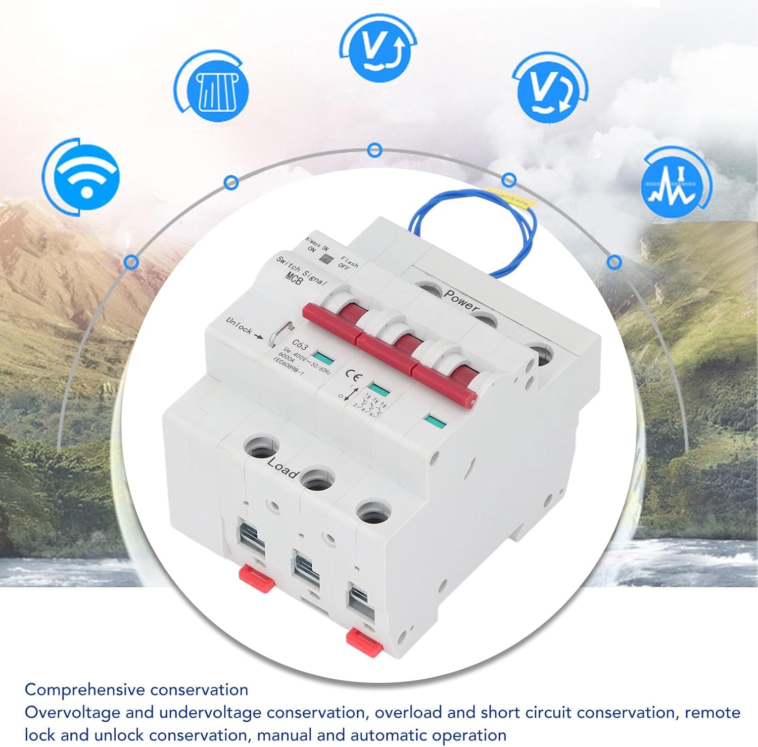
Image depicting the circuit breaker with icons representing its comprehensive protection features, including over/under voltage, overload, short circuit, and remote lock/unlock.
- Over/Under Voltage Protection: Automatically trips the circuit when voltage levels exceed or fall below safe thresholds.
- Overload Protection: Guards against excessive current draw that could damage equipment or wiring.
- Short Circuit Protection: Provides rapid disconnection in the event of a short circuit, preventing severe damage and fire hazards.
- Remote Lock/Unlock: Allows for remote locking or unlocking of the circuit breaker's operation, adding an extra layer of security and control.
- Manual/Automatic Mode: Supports both manual operation and automatic control via the PC network.
6. Maintenance
Regular maintenance helps ensure the longevity and reliable operation of your circuit breaker.
- Visual Inspection: Periodically inspect the circuit breaker for any signs of physical damage, discoloration, or loose connections.
- Cleaning: Keep the circuit breaker clean and free from dust and debris. Use a dry, soft cloth for cleaning. Do not use liquid cleaners.
- Connection Check: Ensure all terminal connections remain tight. Loose connections can lead to overheating and poor performance.
- Function Test: If safe to do so, periodically test the manual switch operation to ensure it moves freely.
7. Troubleshooting
If you encounter issues with your RS485 Smart Circuit Breaker, refer to the following common troubleshooting steps:
- Circuit Breaker Trips Frequently:
- Check for overloaded circuits. Reduce the load if necessary.
- Inspect for short circuits in the wiring or connected appliances.
- Verify that the input voltage is within the specified range (AC400V).
- Cannot Push Handle Up (ON):
- Ensure the input and output wiring direction is correct (upper input, lower output). If reversed, physically reorient the breaker.
- Check if the circuit breaker has tripped due to an overload or short circuit. Resolve the issue before attempting to reset.
- No Remote Control/Monitoring:
- Verify the RS485 wiring connections are correct and secure.
- Ensure the USB to RS485 converter is properly installed and recognized by your PC.
- Check the PC software settings and communication parameters.
- Confirm the control section wires are correctly connected to sockets 1 & 3 (passive) or 2 & 3 (active).
- Device Not Powering On:
- Ensure the main power supply to the circuit breaker is active.
- Check the incoming terminal connection for proper contact.
If the problem persists after following these steps, contact customer support.
8. Warranty and Support
For warranty information, technical support, or service inquiries, please refer to the product packaging or contact the seller/manufacturer directly. Keep your purchase receipt as proof of purchase for warranty claims.