1. Introduction
This manual provides essential information for the safe and efficient operation, maintenance, and troubleshooting of your VEVOR 8.3'' x 29.5'' Benchtop Metal Lathe, Model WM210V-L. Please read this manual thoroughly before operating the machine to ensure proper usage and to prevent injury or damage.

Figure 1: VEVOR 8.3'' x 29.5'' Benchtop Metal Lathe WM210V-L with various accessories including chucks, gears, and tools.
2. Safety Instructions
Always prioritize safety when operating machinery. Failure to follow safety guidelines can result in serious injury or death.
- Read the Manual: Understand all instructions and warnings before operation.
- Personal Protective Equipment (PPE): Always wear safety glasses or a face shield, hearing protection, and appropriate work clothing. Avoid loose clothing, jewelry, and long hair that can get caught in moving parts.
- Work Area: Keep the work area clean, well-lit, and free from obstructions. Ensure adequate ventilation.
- Machine Condition: Inspect the lathe for damage or loose parts before each use. Do not operate a damaged machine.
- Emergency Stop: Familiarize yourself with the location and operation of the emergency stop switch.
- Power Disconnection: Disconnect power before performing any maintenance, adjustments, or when changing accessories.
- Chuck Guard: Ensure the chuck guard is in place and functioning correctly. The machine features a chuck cover power-off switch for added safety.
- Overload Protection: The machine is equipped with overload protection. Do not attempt to bypass this feature.
- Secure Workpiece: Always ensure the workpiece is securely clamped in the chuck or between centers.
- Tooling: Use sharp, correctly ground tools. Ensure tools are properly secured in the tool post.
- Supervision: Never leave the machine running unattended.
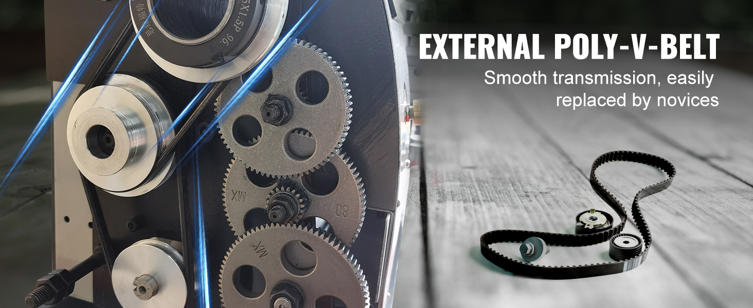
Figure 2: The VEVOR Lathe incorporates multiple safety features, including overload protection, a high-speed reverse safety device, and a chuck cover disconnection protection switch.
3. Setup
3.1 Unpacking and Inspection
- Carefully remove the lathe and all accessories from the packaging.
- Check for any visible damage during transit. Report any damage to the carrier immediately.
- Verify all components listed in the packing list are present.
3.2 Placement
- Place the lathe on a sturdy, level workbench capable of supporting its weight (approximately 197 lbs / 89 kg).
- Ensure sufficient clearance around the machine for safe operation and maintenance.
- The V-shaped precision steel guide ensures stability during operation.
3.3 Power Connection
- Connect the lathe to a grounded 110V / 60Hz AC power outlet.
- Ensure the power switch is in the OFF position before plugging in the machine.
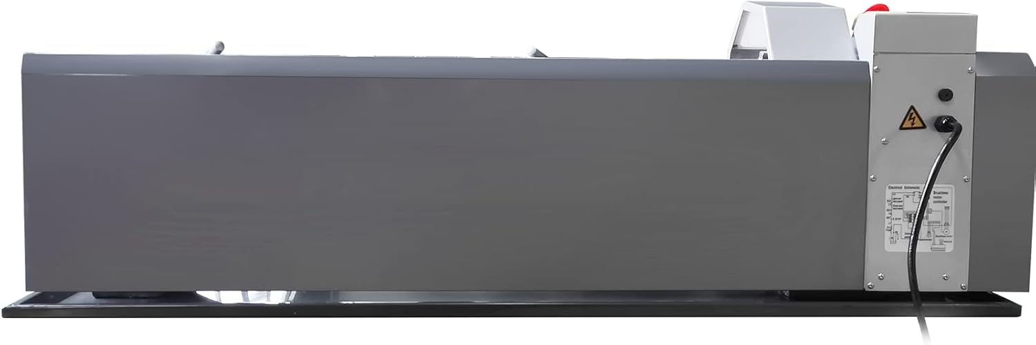
Figure 3: Rear view of the lathe, illustrating the power connection point and main control panel security switch.
4. Operation
4.1 Control Panel Overview
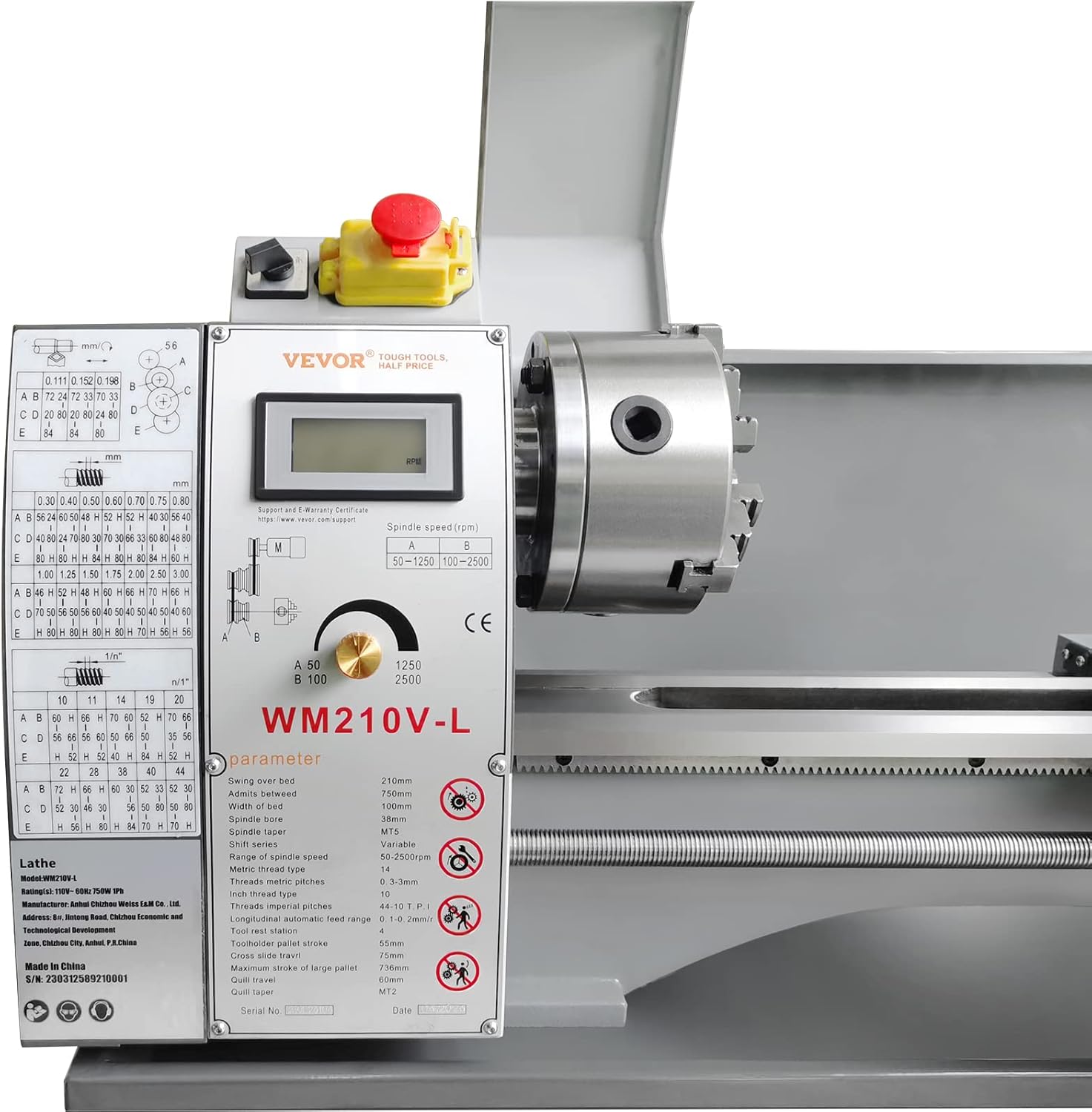
Figure 4: Detailed view of the control panel, featuring the digital display for spindle speed and the speed adjustment knob.
4.2 Spindle Speed Adjustment
The VEVOR WM210V-L features a continuously variable speed control with two gear options:
- High Gear (H): 100-2500 RPM
- Low Gear (L): 50-1250 RPM
Use the gear selector to choose between high and low ranges. The intelligent digital display provides accurate real-time spindle speed readings. Adjust the speed using the control knob on the panel.
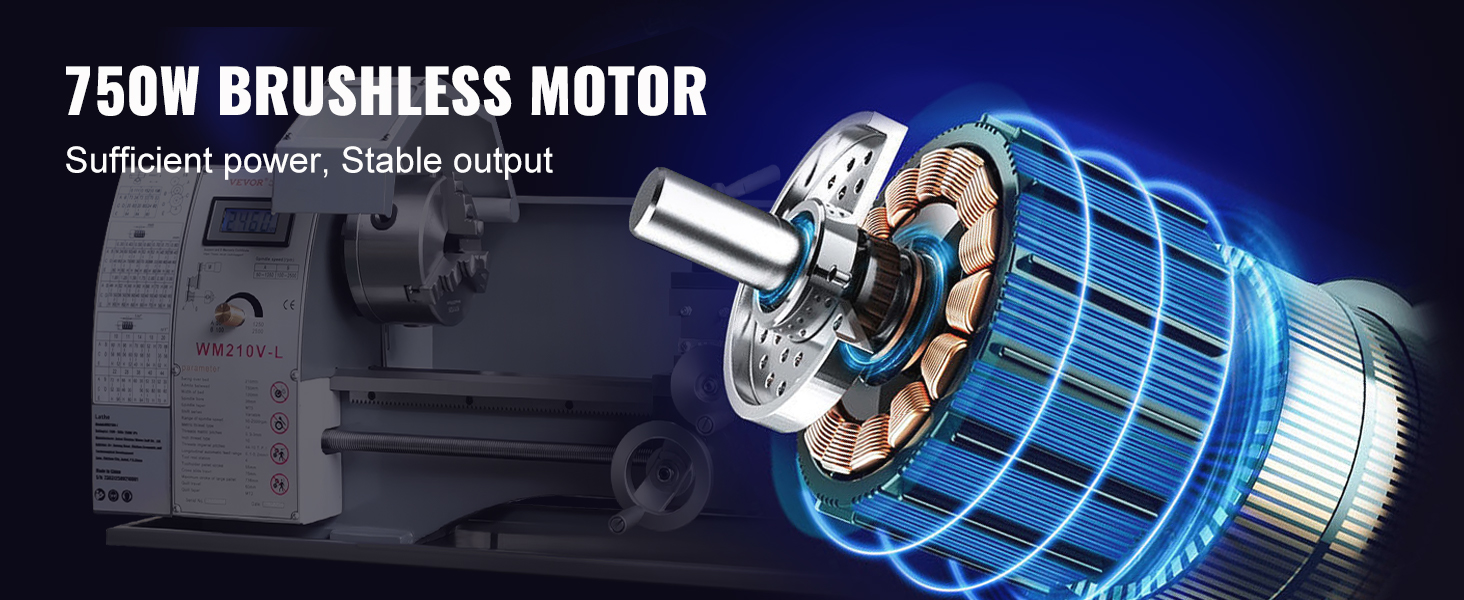
Figure 5: The lathe offers continuously variable speed control, electronically managed and displayed digitally for precise adjustments.
4.3 Workpiece Clamping
The lathe is equipped with a 4.9-inch 3-jaw metal chuck for multi-directional clamping. Ensure the workpiece is securely fastened before starting any operation to prevent it from dislodging.
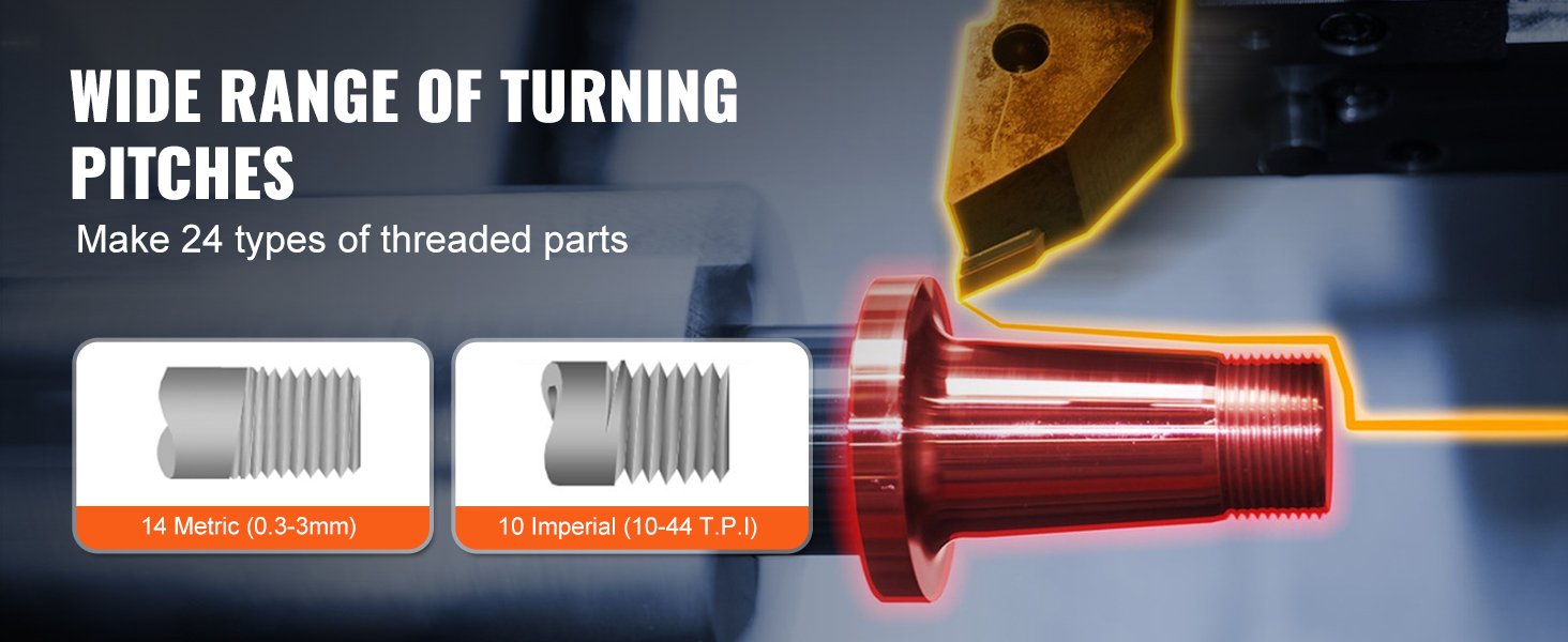
Figure 6: The 4.9-inch 3-jaw metal chuck provides stable and secure clamping for various workpieces.
4.4 Thread Cutting
The lathe supports a wide range of turning pitches, capable of creating 24 different types of threads:
- Metric System: 14 types (ranging from 0.3-3mm)
- Imperial System: 10 types (ranging from 10-44 TPI)
Refer to the threading chart on the machine's control panel for specific gear configurations required for each thread type.
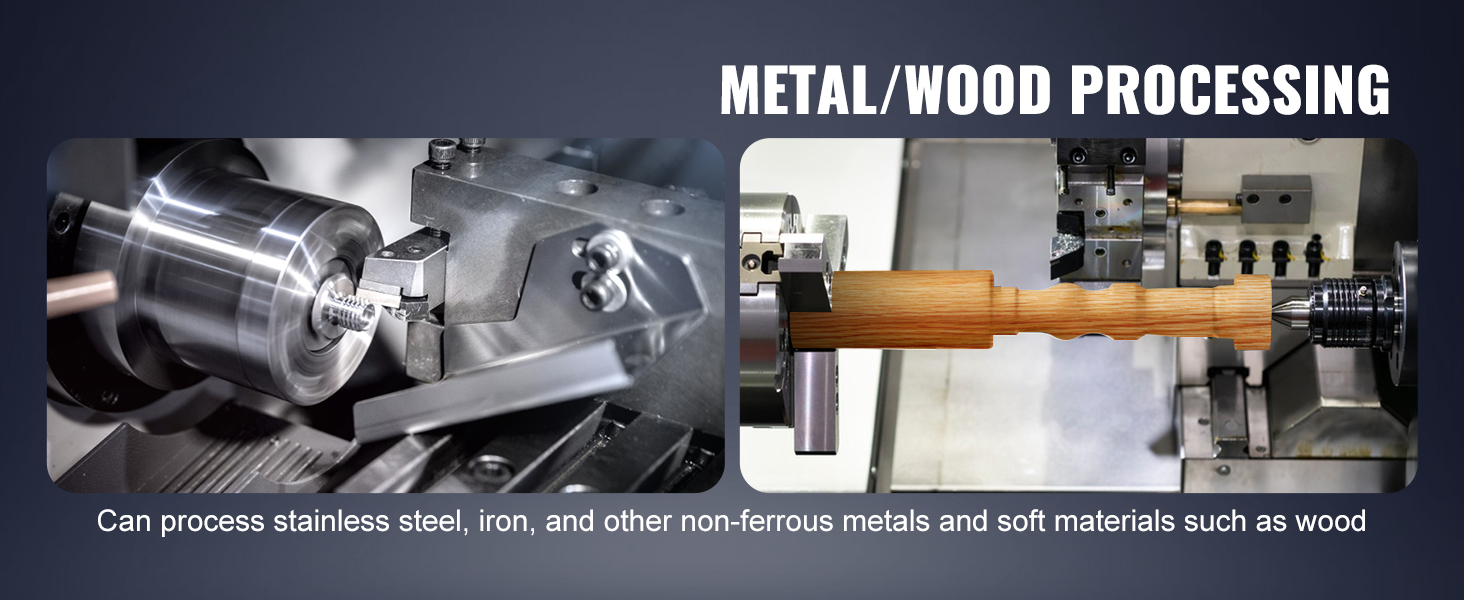
Figure 7: The lathe supports a wide range of turning pitches, enabling the creation of 24 different types of threads, including both metric and imperial standards.
4.5 General Machining Operations
The VEVOR WM210V-L is suitable for various machining tasks on both metal and soft materials like wood, including:
- Turning
- Drilling
- Thread Turning
- Knurling
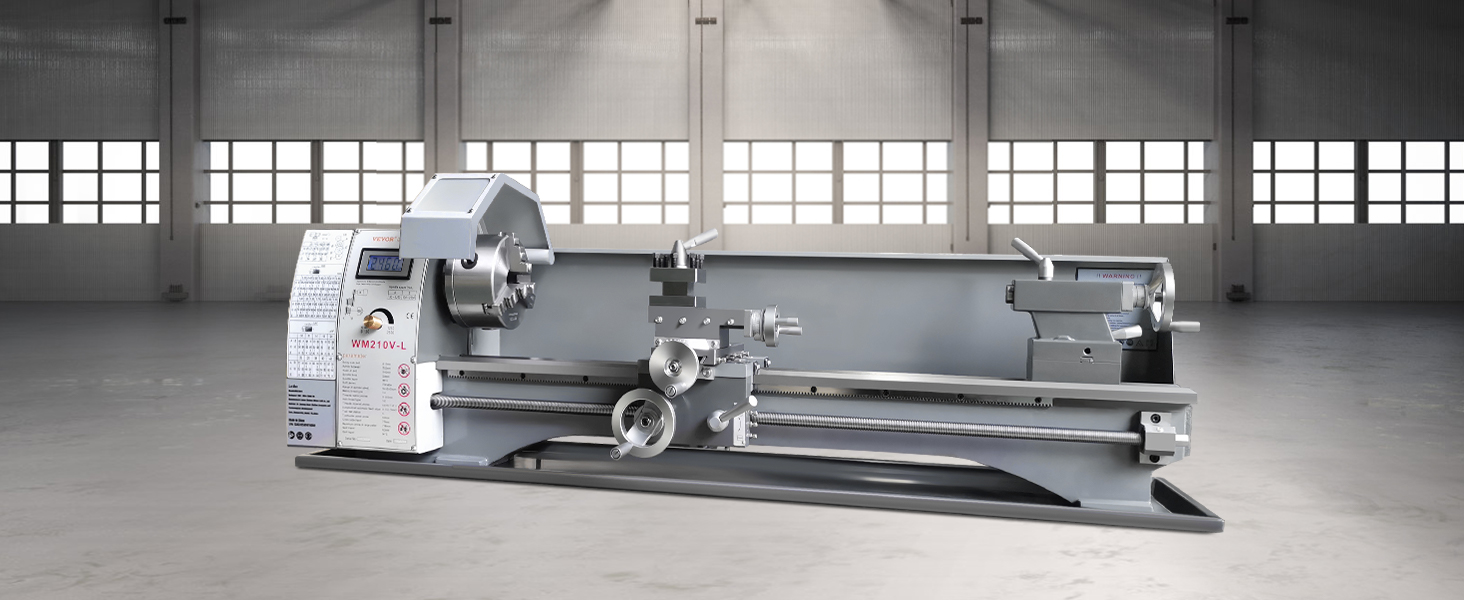
Figure 8: Examples of machining fine parts, including turning, drilling, thread turning, and knurling operations.
5. Maintenance
Regular maintenance ensures the longevity and optimal performance of your lathe. Always disconnect power before performing maintenance.
5.1 Cleaning
- After each use, clean chips and debris from the bed, cross slide, and other moving parts using a brush or shop vacuum.
- Wipe down all surfaces with a clean cloth. Avoid using harsh chemicals that may damage painted surfaces.
5.2 Lubrication
- Regularly lubricate the lead screw, cross slide, and other sliding surfaces with appropriate machine oil.
- Check and maintain the oil level in the gearbox if applicable.
5.3 Gear Inspection
The lathe is equipped with durable metal gears. Periodically inspect the gears for wear or damage. The external Poly-V-Belt system is designed for smooth transmission and easy replacement.
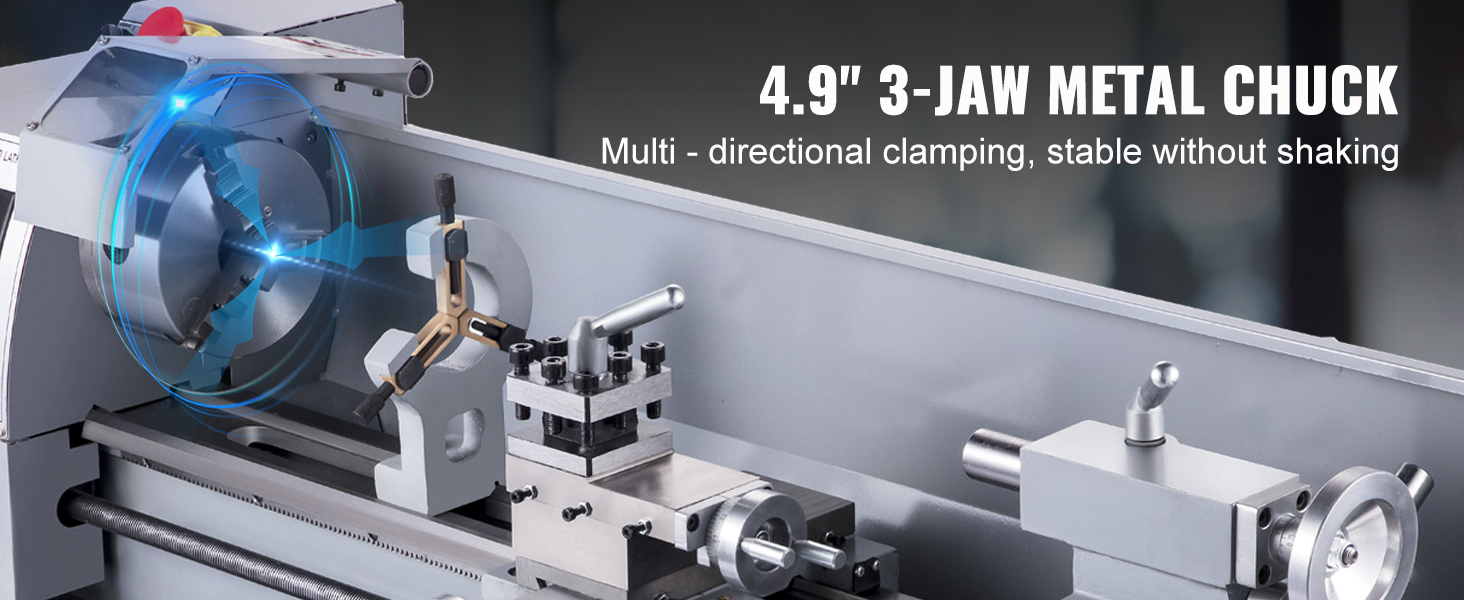
Figure 9: The lathe features heavy-duty metal gears, designed for extended durability compared to nylon alternatives.
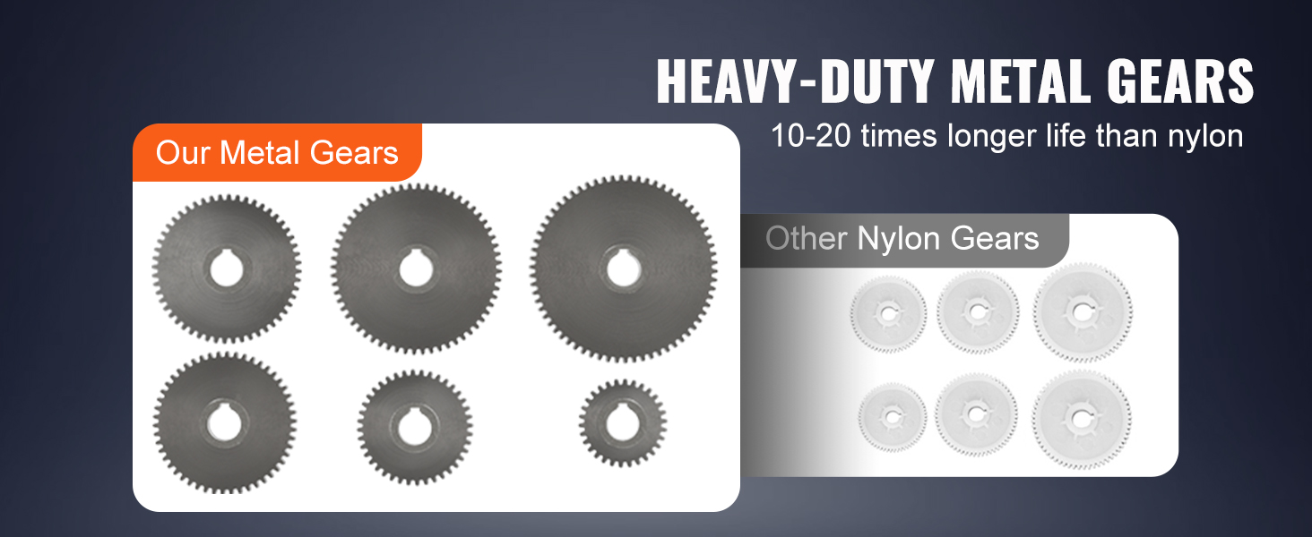
Figure 10: The external Poly-V-Belt system ensures smooth power transmission and simplifies belt replacement.
5.4 Brushless Motor
The 750W brushless motor provides consistent power and eliminates the need for brush replacements, reducing maintenance requirements.
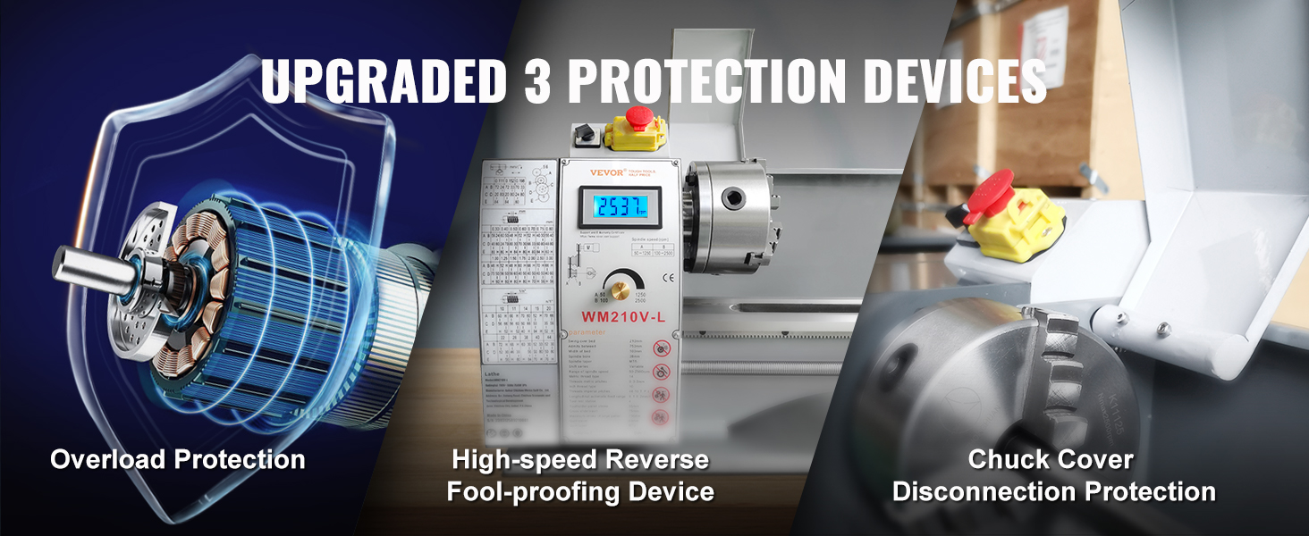
Figure 11: The 750W brushless motor delivers sufficient and stable power output for various machining tasks.
6. Troubleshooting
This section addresses common issues you might encounter with your metal lathe.
| Problem | Possible Cause | Solution |
|---|---|---|
| Machine does not power on | No power supply; Emergency stop engaged; Main control panel security switch off; Chuck cover open. | Check power connection; Release emergency stop; Ensure main control panel security switch is ON; Close chuck cover. |
| Spindle not rotating | Motor overload protection activated; Belt loose or broken; Gear selector not fully engaged. | Reduce load, allow motor to cool; Inspect and adjust/replace belt; Ensure gear selector is firmly in position. |
| Inaccurate cuts / Excessive vibration | Loose workpiece; Dull cutting tool; Improper tool setup; Loose machine components; Unlevel machine. | Secure workpiece firmly; Sharpen or replace tool; Ensure tool is centered and rigid; Check and tighten all fasteners; Verify machine is level on a stable surface. |
| Threading issues | Incorrect gear setup; Lead screw not engaged; Improper tool for threading. | Consult threading chart for correct gear configuration; Ensure lead screw is engaged; Use appropriate threading tool. |
7. Specifications
Detailed technical specifications for the VEVOR WM210V-L Metal Lathe.

Figure 12: Overview of the VEVOR Metal Lathe's dimensions and core specifications.
| Feature | Specification |
|---|---|
| Main Material | HT200 Cast Iron |
| Swing Over Bed | 211 mm / 8.3 inches |
| Distance Between Centers | 750 mm / 29.5 inches |
| Spindle Taper | MT5 |
| Tail Stock Taper | MT2 |
| Motor Power | 750W Brushless Motor |
| Voltage | 110V / 60 Hz |
| Spindle Speed (High Gear) | 100-2500 RPM |
| Spindle Speed (Low Gear) | 50-1250 RPM |
| Chuck Diameter | 125 mm / 4.9 inches (3-jaw) |
| Spindle Bore | 38 mm / 1.49 inches |
| Metric Thread Pitches | 0.3-3 mm (14 types) |
| Imperial Thread Pitches | 10-44 TPI (10 types) |
| Product Dimensions (L x W x H) | 1200 x 340 x 360 mm / 47.2 x 13.4 x 14.2 inches |
| Net Weight | 79 kg / 174 lbs |
| Included Components | 1 x Oil Pan, 1 x Oiler, 2 x Open Spanner, 1 x Crescent Wrench, 1 x Cross Screwdriver, 1 x Flat Screwdriver, 1 x Hex Socket Wrenches (2.5, 3, 4, 5, 6), 2 x Dead Center (MT2/MT5), 1 x Pulley Set, 1 x Tool Box |
8. Warranty and Support
8.1 Warranty Information
VEVOR products are designed for durability and performance. For specific warranty terms and conditions, please refer to the warranty card included with your product or visit the official VEVOR website. Keep your purchase receipt as proof of purchase for any warranty claims.
8.2 Customer Support
For technical assistance, spare parts, or any questions regarding your VEVOR Metal Lathe, please contact VEVOR customer support through their official website or the contact information provided in your product packaging. When contacting support, please have your model number (WM210V-L) and serial number ready.