1. Introduction and Overview
This manual provides comprehensive instructions for the Binardat Industrial 12 Port Full Gigabit Solar POE Managed Switch. This device is engineered for robust networking in demanding industrial environments, offering 12 Gigabit ports, Power over Ethernet (PoE) capabilities, and advanced Layer 3 management features. It supports a wide DC input voltage range (8V-57V) and includes a built-in voltage booster for 48V PoE output, making it suitable for solar-powered systems and various vehicle applications. Its durable IP40-rated design ensures reliable operation in harsh conditions.
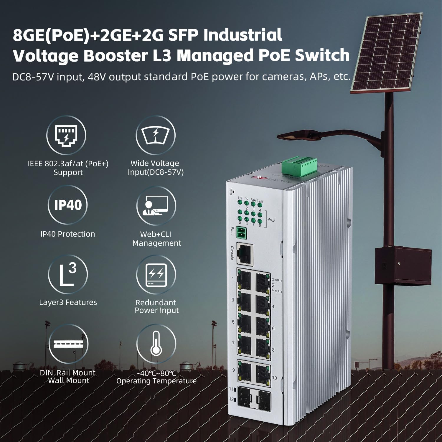
Figure 1.1: Overview of the Binardat Industrial PoE Switch, showcasing its 8 PoE ports, 2 Gigabit uplink ports, 2 SFP slots, and key features like wide voltage input, IP40 protection, Layer 3 capabilities, redundant power input, and wide operating temperature range.
2. Package Contents
Verify that your package contains all the following items:
- POE Din rail Switch
- Console Cable
- User Manual
- Din/wall Mount Kit
- Phoenix terminal
3. Key Features
- DC8V~57V POE Voltage Booster: Supports a wide DC input voltage range from 8V to 57V. Features two redundant power inputs (P1 and P2) with automatic fault switching via a phoenix terminal, allowing connection to solar power supplies or batteries. Outputs IEEE802.3af/at PoE 44-57V with a built-in voltage booster.
- 12 Gigabit Ports: Includes 8 gigabit PoE Ethernet ports (10/100/1000Mbps auto-adaptive), 2 gigabit uplink ports, and 2 Gigabit SFP slots (supports single/multi-fiber, module not included). Offers a 24Gbps switching capacity for high performance.
- IEEE802.3af/at PoE: PoE ports 1-8 support IEEE802.3af/at standards, providing a maximum of 30W per port with a total power budget of 240W. PoE pin assignment is 1/2 (+) and 3/6 (-). Note that passive 24V PoE is not supported.
- L3 Managed Capabilities: Offers comprehensive L2/L3 management via Web and Command Line Interface (CLI). Features include IPv4/IPv6, ARP, Static Routing, DHCP, VLAN, MAC table management, ACL/QoS, port security, flow control, STP/RSTP/MSTP spanning tree, storm suppression, traffic statistics, status query, and support for ring/star network topologies.
- Industrial Design: IP40-rated industrial housing, suitable for DIN rail or wall mounting. Features a fanless design and operates within a wide temperature range of -40°C to 75°C (-40°F to 185°F). Includes anti-lightning, anti-static, and anti-overload protection for enhanced durability.

Figure 3.1: Smart PoE+ Support. The switch provides 15.4W per port for IEEE 802.3af devices (e.g., 802.11n APs, IP Phones, IP Cameras) and up to 30W per port for IEEE 802.3at devices (e.g., IP Video Phones, 802.11ac WiFi APs, PTZ HD IP Cameras).

Figure 3.2: Industrial Design. The switch features a compact size (6.73 x 4.72 x 1.97 inches), 4KV lightning protection, a fanless and sturdy housing, and supports both DIN rail and wall mounting.
4. Setup and Installation
4.1 Mounting the Switch
The switch supports both DIN rail and wall mounting. Use the included mounting kit to secure the device in your desired location. Ensure adequate ventilation around the switch, especially given its fanless design, to maintain optimal operating temperature.
4.2 Power Connection
The switch requires a DC input voltage between 8V and 57V. Connect your power source to the phoenix terminal. The device features two redundant power inputs (P1 and P2) for enhanced reliability. If one power source fails, the switch automatically switches to the other. Ensure correct polarity when connecting the power cables.

Figure 4.1: Dual Redundant Power Inputs. The phoenix terminal allows for two independent DC power inputs (P1 and P2) for fault tolerance, along with overcurrent and reverse connection protection.

Figure 4.2: DC 8-57V Input to 48V PoE Output. Illustrates how the switch can take power from solar systems (PV 18V, DC 12V from battery), vehicle PoE supply (DC 12V input), or DC 24V input, and boost it to 48V PoE output for IEEE802.3af/at devices like IP phones, wireless APs, and IP cameras.
4.3 Network Connections
Connect your network devices (e.g., IP cameras, wireless access points, computers) to the 8 Gigabit PoE Ethernet ports. Use the 2 Gigabit uplink ports or 2 SFP slots for connecting to your core network or other switches. Ensure all cables are securely connected.
5. Operation
5.1 Initial Power On
Once power is connected, the switch will initiate its boot sequence. Observe the LED indicators for status. The Power LED should illuminate, and port LEDs will indicate connection status and activity.
5.2 PoE Functionality
The 8 PoE ports automatically detect and provide power to compatible IEEE802.3af/at powered devices (PDs). If a non-PoE device is connected, the port will function as a standard Ethernet port without supplying power.
5.3 LED Indicators
Refer to the device's front panel for LED indicators. These typically include:
- Power LED: Indicates power status.
- PoE LED: Indicates PoE power delivery status for each port.
- Link/Act LED: Indicates network link status and data activity for each port.
6. Management
The Binardat Industrial Switch offers comprehensive management options via a Web-based Graphical User Interface (GUI) and a Command Line Interface (CLI).

Figure 6.1: Flexible Management and Operation. The image displays both the Web interface and Command Line Interface (CLI) for managing the switch. Default IP: 192.168.2.1, User Name: admin, Password: admin.
6.1 Web Interface Access
To access the Web GUI:
- Connect a computer to any Ethernet port of the switch.
- Configure your computer's IP address to be in the same subnet as the switch (e.g., 192.168.2.x, where x is not 1).
- Open a web browser and enter the default IP address: 192.168.2.1
- Enter the default username: admin and password: admin.
- Upon successful login, you can configure various network settings, including VLANs, QoS, port security, and PoE settings.
6.2 Command Line Interface (CLI) Access
The CLI can be accessed via the console port using the included console cable or remotely via Telnet/SSH. Refer to the detailed CLI guide for specific commands and configurations.
6.3 Layer 3 Management Features
The switch supports advanced Layer 3 features for complex network architectures:
- Static Routing: Configure static routes to direct traffic between different IP subnets.
- DHCP Server/Relay: Manage IP address assignment within your network.
- VLAN: Create Virtual Local Area Networks to segment traffic and enhance security.
- QoS (Quality of Service): Prioritize critical network traffic (e.g., VoIP, video) to ensure optimal performance.
- STP/RSTP/MSTP: Implement Spanning Tree Protocols to prevent network loops and ensure redundancy.
- ACL (Access Control List): Define rules to filter network traffic based on various criteria.
- SNMP: Monitor network devices remotely using Simple Network Management Protocol.

Figure 6.2: Static Route. This animation illustrates how static routing enables communication between two switches configured with different IP subnets (e.g., 192.168.1.1/24 and 192.168.2.1/24).

Figure 6.3: VLAN Configuration. This animation demonstrates how VLANs can segment network traffic, allowing multiple cameras to be logically separated into different VLANs (e.g., VLAN 1, VLAN 2) even when connected to the same physical switch.

Figure 6.4: Quality of Service (QoS). This animation visually represents how QoS prioritizes different types of network traffic, ensuring that critical data like voice and video receive preferential bandwidth over less time-sensitive data like email or file transfers.
7. Applications and Use Cases
The Binardat Industrial Switch is versatile and suitable for various applications:
- Solar Powered Systems: Compatible with DC12V, DC18V, and DC36V inputs, making it ideal for remote installations powered by solar panels and batteries.
- Mobile Applications: Suitable for RVs, cars, trucks, and buses with DC12V inputs, providing reliable networking on the go.
- VoIP and Access Control Systems: Supports DC24V inputs, perfect for powering VoIP phones, access control devices, and other low-voltage equipment.
8. Specifications
| Attribute | Value |
|---|---|
| Brand | Binardat |
| Model Number | 12 Port Gigabit PoE Solar |
| Number of Ports | 12 (8 PoE Gigabit, 2 Gigabit Uplink, 2 SFP) |
| Data Transfer Rate | 12000 Megabits Per Second (12 Gbps) |
| Switching Capacity | 24 Gbps |
| PoE Standard | IEEE802.3af/at |
| Max PoE Power Per Port | 30W |
| Total PoE Budget | 240W |
| Input Voltage | 8V - 57V (DC) |
| Output Voltage (PoE) | 44V - 57V (DC) |
| Case Material | Metal |
| IP Rating | IP40 |
| Operating Temperature | -40°C to 75°C (-40°F to 185°F) |
| Item Weight | 1.3 Kilograms (2.86 pounds) |
| Package Dimensions | 8.66 x 6.69 x 3.54 inches |
| Mounting Options | DIN Rail, Wall Mount |
| Included Components | Console Cable, Din/wall Mount Kit, POE Din rail Switch, Phoenix terminal, User Manual |
9. Troubleshooting
If you encounter issues with your Binardat Industrial Switch, consider the following troubleshooting steps:
- No Power:
- Verify that the DC power source is connected correctly to the phoenix terminal and is within the 8V-57V range.
- Check the power cables for damage and ensure proper polarity.
- Confirm that the power source itself is functional.
- No Link on Port:
- Ensure the Ethernet cable is securely connected at both ends.
- Test with a different Ethernet cable.
- Verify the connected device is powered on and functioning correctly.
- For SFP ports, ensure the SFP module is correctly inserted and compatible.
- PoE Device Not Powering On:
- Confirm the connected device is an IEEE802.3af/at compliant Powered Device (PD). Passive 24V PoE is not supported.
- Check the PoE LED for the specific port; if it's off, PoE power is not being delivered.
- Ensure the total PoE budget (240W) is not exceeded by all connected devices.
- Try connecting the PoE device to a different PoE port.
- Cannot Access Web Interface:
- Ensure your computer's IP address is in the same subnet as the switch (default 192.168.2.x).
- Verify you are using the correct default IP address (192.168.2.1), username (admin), and password (admin).
- Clear your browser's cache or try a different browser.
- If the IP address was changed and forgotten, a factory reset may be necessary (refer to the reset procedure in the full manual).
10. Safety Information
Please read and follow these safety guidelines to prevent damage to the device or injury to yourself:
- Always disconnect power before cleaning or servicing the switch.
- Do not expose the device to water or excessive moisture.
- Ensure proper grounding to prevent electrical shock.
- Do not open the device casing; there are no user-serviceable parts inside.
- Use only approved power sources within the specified voltage range.
- Install the switch in a well-ventilated area, even though it is fanless, to aid in heat dissipation.