Introduction
The DIYmall ESP32-2424S012C is a compact 1.3-inch capacitive touch IPS TFT LCD module. It integrates an ESP32-C3-MINI-1U single-core microcontroller unit (MCU), offering built-in Wi-Fi and Bluetooth Low Energy (BLE) functionalities. This module features a 240x240 resolution display, 4MB flash memory, and a main frequency up to 160MHz. It is designed for development in Arduino IDE and ESP-IDF environments, providing a versatile platform for various embedded projects.
Setup Instructions
This section outlines the steps for initial setup of your ESP32-2424S012C module.
1. Component Identification
Familiarize yourself with the module's key components and interfaces:
- Type-C USB Port: Used for power supply, data communication, and programming.
- BAT+ (JST1.25-2P) Connector: For connecting an external lithium battery.
- REST Button: Resets the module.
- BOOT Button: Used to enter bootloader mode for flashing new firmware.
- SH1.0-4P Connector: An additional IO port interface.

Figure 1: External view of the ESP32 module, highlighting the reset (REST) and boot (BOOT) buttons, the battery interface (BAT+ JST1.25-2P), and the Type-C USB port for power and data.

Figure 2: Internal view of the circuit board, identifying key components such as the ESP32-C3-MINI-1U microcontroller, REST and BOOT buttons, a switch, the battery interface, SH1.0-4P connector, and the Type-C USB port.
2. Initial Power-Up
Connect the module to a 5V power source using the Type-C USB cable. The module comes with a factory pre-programmed sample program, which should start running automatically upon power-up, demonstrating the display's capabilities.
3. Battery Connection (Optional)
If using a lithium battery, connect it to the BAT+ (JST1.25-2P) interface. The module includes a lithium battery charging interface with overcharge and over-discharge protection, allowing for safe charging and discharging cycles.
Operating Instructions
The ESP32-2424S012C module is designed for custom application development. Here are general guidelines for operation:
1. Development Environment
To develop custom applications, you will typically use the Arduino IDE or ESP-IDF. Ensure you have the necessary ESP32 board support packages and toolchains installed.
2. Flashing Firmware
To upload new firmware:
- Connect the module to your computer via the Type-C USB port.
- Press and hold the BOOT button.
- While holding BOOT, briefly press and release the REST button.
- Release the BOOT button. The module is now in bootloader mode, ready to receive new firmware from your development environment.
3. Using Wi-Fi and BLE
The integrated ESP32-C3-MINI-1U supports Wi-Fi (802.11b) and BLE connectivity. You can program the module to connect to networks, send/receive data, and interact with other Bluetooth devices using the respective libraries in your chosen development environment.
4. Capacitive Touch Display
The 1.3-inch IPS TFT LCD features capacitive touch functionality. Your custom firmware can detect touch inputs on the screen, enabling interactive user interfaces.
Maintenance
Proper maintenance ensures the longevity and reliable operation of your module.
- Cleaning: Use a soft, dry cloth to clean the display and module casing. Avoid abrasive cleaners or solvents.
- Storage: Store the module in a dry, dust-free environment away from direct sunlight and extreme temperatures.
- Battery Care: If using a lithium battery, ensure it is charged and discharged within its specified voltage range. The module's built-in protection helps prevent overcharge and over-discharge, but external battery management practices should also be followed.
- Firmware Updates: Regularly check for updated firmware or libraries from the ESP32 community or DIYmall to benefit from improvements and bug fixes.
Troubleshooting
If you encounter issues with your ESP32-2424S012C module, refer to the following common problems and solutions:
1. Module Does Not Power On
- Check USB Connection: Ensure the Type-C USB cable is securely connected to both the module and a working power source (e.g., computer USB port, 5V USB adapter).
- Verify Power Source: Test the USB port or adapter with another device to confirm it provides power.
- Battery Check: If using a battery, ensure it is charged and properly connected.
2. Cannot Upload Firmware
- Bootloader Mode: Ensure you are correctly entering bootloader mode by holding the BOOT button, pressing REST, and then releasing BOOT.
- Driver Installation: Verify that the necessary USB-to-serial drivers (e.g., CP210x or CH340) are installed on your computer.
- Correct Port Selection: In your Arduino IDE or ESP-IDF, ensure the correct serial port for the module is selected.
- Cable Quality: Try a different Type-C USB cable, as some cables are for charging only and do not support data transfer.
3. Display Issues (No Image, Incorrect Colors)
- Power Supply: Ensure the module is receiving adequate power.
- Firmware: Verify that your uploaded firmware correctly initializes and drives the GC9A01 display controller.
- Connections: While the display is integrated, ensure no physical damage to the screen or internal connections.
4. Wi-Fi or BLE Connectivity Problems
- Antenna: Ensure the integrated antenna is not obstructed.
- Code Logic: Double-check your Wi-Fi or BLE initialization and connection code for errors.
- Environment: Test in an environment with minimal wireless interference.
Specifications
Detailed technical specifications for the DIYmall ESP32-2424S012C module:
| Feature | Specification |
|---|---|
| Brand | DIYmall |
| Model Name | ESP32-2424S012C-I-Y(B) |
| Display Size | 1.3 inch (3.3 cm) |
| Display Type | IPS TFT LCD |
| Resolution | 240 x 240 pixels |
| Screen Color | 16-bit color |
| Driver Chip | GC9A01 |
| Microcontroller | ESP32-C3-MINI-1U (Single-core MCU) |
| CPU Speed | Up to 160 MHz |
| Memory Storage Capacity | 4 MB Flash |
| Connectivity Technology | Wi-Fi, Bluetooth Low Energy (BLE) |
| Wireless Standard | 802.11b |
| Operating Voltage | 5V |
| Power Consumption | Approximately 100 mA |
| Operating Temperature | -20°C to 70°C |
| Module Dimensions | 38.5 x 37.0 mm |
| Included Components | 1 x 1.3-inch ESP32 Capacitive Touch Screen Module |
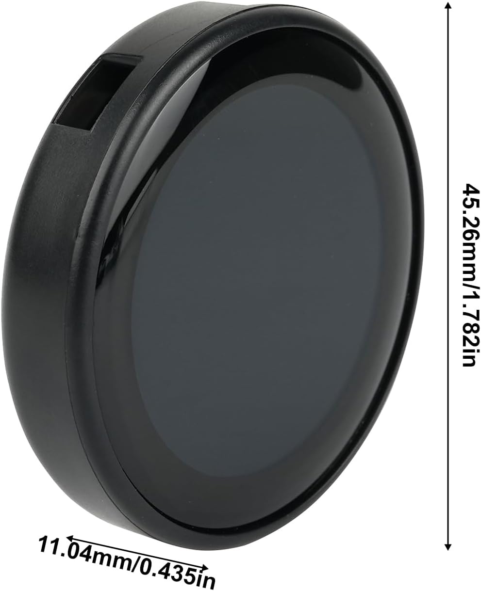
Figure 3: Physical dimensions of the module, showing a height of 45.26mm (1.782 inches) and a thickness of 11.04mm (0.435 inches).

Figure 4: A view from the bottom of the module, clearly showing the Type-C USB port for connectivity.

Figure 5: Detailed schematic diagram of the module, including the ESP32 microcontroller, LCD connections, Type-C interface, and power management circuitry for advanced users and developers.
Warranty and Support
For warranty information or technical support, please refer to the official DIYmall website or contact their customer service directly. Specific warranty terms and support channels may vary.


