1. Introduction
This manual provides detailed instructions for the installation, operation, and maintenance of the L.A Ornamental Beninca Telescopic Sliding Gate System, designed for two-door configurations with an opening of 28ft and a total gate size of 32ft. Please read this manual thoroughly before beginning installation or operation to ensure proper function and safety.
2. Safety Information
Important Safety Instructions:
- Always disconnect power before performing any service or maintenance.
- Installation should be performed by qualified personnel only.
- Ensure all components are securely fastened according to instructions.
- Keep hands and clothing clear of moving parts during operation.
- Do not allow children to play near the gate system.
- Regularly inspect the system for wear, damage, or loose components.
3. System Components
The complete kit includes the following components:
- 9 x 281.11 Pair of Galvanized Cable Covers (38x20x1.5 L 1200 MM / 4Ft)
- 1 x 282.501 Galvanized Fixed Pulley Box for 5MM Cable
- 1 x 282.511 Galvanized Movable Pulley Box for 5MM Cable
- 1 x 282.521 Galvanized Cable Ground Fixing Bracket
- 1 x 282.531 Galvanized Connection Gate Bracket Between Panels
- 10 x 283.011 Galvanized L-Bracket (42x40x3 for U-Track 283.3xx)
- 2 x 283.013 Galvanized Track Cap
- 3 x 283.323 Galvanized U-Track (38x38x3 for Ø 30 MM Rollers 6 FT)
- 2 x 283.302 Galvanized Guide Bracket with 4 30MM Nylon Rollers
- 1 x 283.201 Adjustable Guide Plate to be Fixed with 3 Rollers
- 4 x 109.120T Galvanized Wheel with Internal Support, V Groove, 1 Bearing
- 40 ft x 284.503 Stainless Steel 5MM Cable
- 11 x V Track Italy 6ft

Figure 3.1: Exploded view of all components included in the L.A Ornamental Beninca Telescopic Sliding Gate System kit. This image illustrates the various parts such as cable covers, pulley boxes, brackets, U-tracks, guide brackets, wheels, and cables, laid out for identification.

Figure 3.2: Labeled diagram showing the main components and their respective part numbers within the telescopic sliding gate system. Key components like 283.013 Track Cap, 283.011 L-Bracket, 283.323 U-Track, 283.302 Guide Bracket, 283.201 Adjustable Guide Plate, 282.511 Movable Pulley Box, 282.501 Fixed Pulley Box, 284.503 Stainless Steel Cable, 282.521 Cable Ground Fixing Bracket, 282.531 Connection Gate Bracket, 109.120T Galvanized Wheel, and V-Tracks are identified.
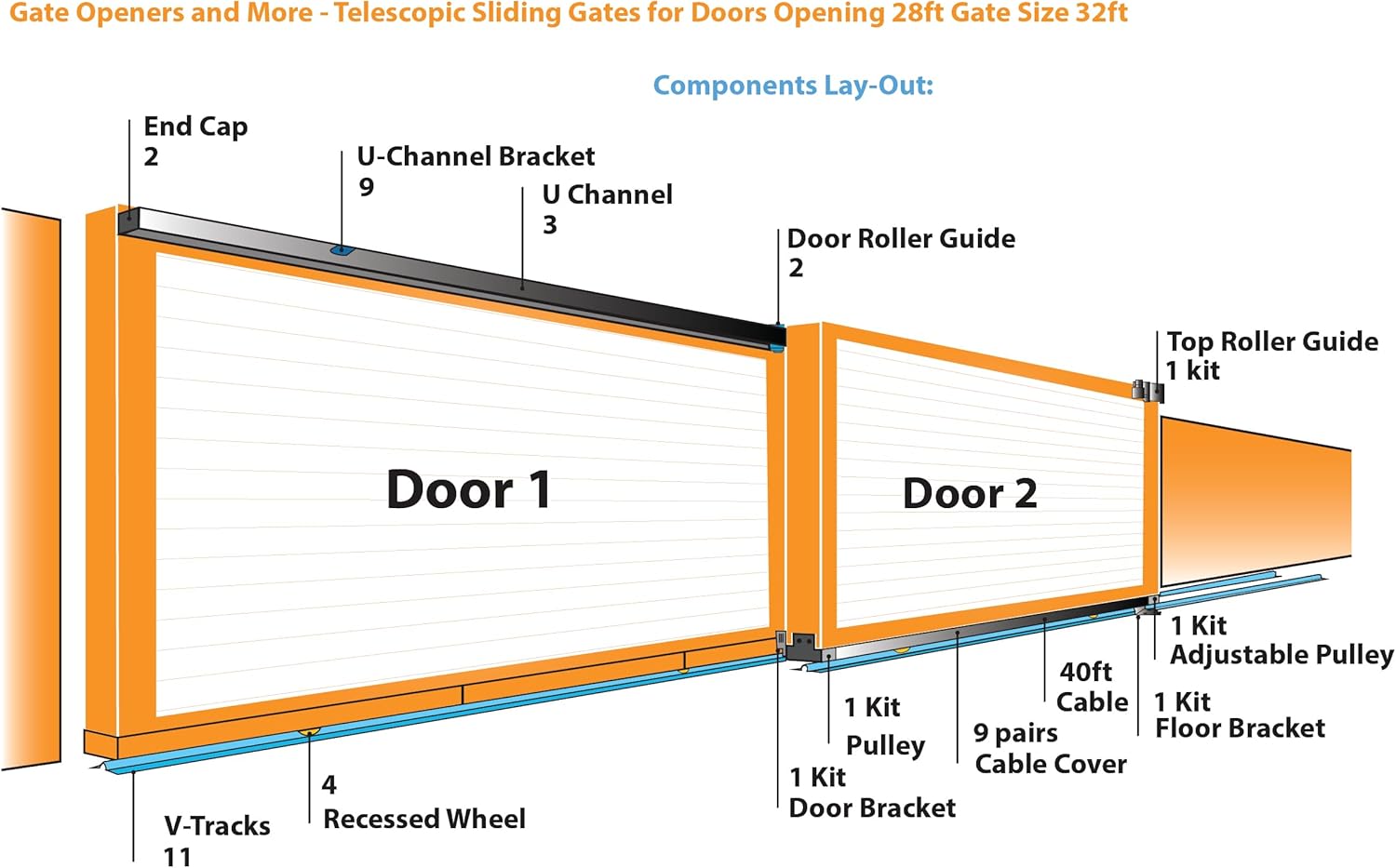
Figure 3.3: Component layout diagram for a two-door telescopic sliding gate system. This illustration indicates the quantity and general placement of major components such as End Caps, U-Channel Brackets, U Channels, Door Roller Guides, Top Roller Guide, Adjustable Pulley, Floor Bracket, Pulley, Door Bracket, Recessed Wheels, V-Tracks, and Cable Covers.
4. Setup and Installation
This section outlines the steps for installing the telescopic sliding gate system. Ensure all safety precautions are followed.
4.1 Pre-Installation Checks
- Verify all components listed in Section 3 are present and undamaged.
- Ensure the gate opening and surrounding area are clear and level.
- Confirm the gate panels are constructed with the recommended frame size.
4.2 Gate Panel Dimensions and Overlap
For a 2-panel system, the length of each door (LA) is calculated based on the opening width and the required overlap (S).

Figure 4.1: Diagram showing the calculation for the length of each gate panel (LA) in a 2-panel system. LA = [(A+B)/2] + S, where A and B represent the total opening width and S is the overlapping distance between the two gate panels. This formula ensures proper coverage and function.
The recommended frame size for the gate panels is 3 inches wide x 6 inches high. Minimum overlapping 'S' is 18 inches for small gates and 36 inches for larger gates (2x door-guides).

Figure 4.2: This image provides a table with recommended dimensions for gate frames (B, S, T in mm) based on the gate opening (A in m). It also illustrates the cross-section of the gate frame and the pulley box attachment, highlighting the frame thickness 'T' for stability and pulley box compatibility.
Recommended frame thickness "T" is 3 inches for better stability and to match pulley box width.
4.3 Component Assembly Sequence
- Install the V-Tracks (11 pieces) along the gate path. Ensure they are level and securely anchored to the ground.
- Attach the 109.120T Galvanized Wheels (4 pieces) to the bottom of the gate panels.
- Mount the 283.323 Galvanized U-Tracks (3 pieces) to the top of the gate structure using the 283.011 Galvanized L-Brackets (10 pieces).
- Install the 283.302 Galvanized Guide Brackets (2 pieces) with nylon rollers to guide the gate panels.
- Position the 282.501 Galvanized Fixed Pulley Box and 282.511 Galvanized Movable Pulley Box according to the system design for cable routing.
- Secure the 282.521 Galvanized Cable Ground Fixing Bracket and 282.531 Galvanized Connection Gate Bracket between panels.
- Route the 284.503 Stainless Steel 5MM Cable (40 ft) through the pulley system as per the specific telescopic gate mechanism.
- Install the 281.11 Galvanized Cable Covers (9 pairs) to protect the cables.
- Attach the 283.013 Galvanized Track Caps (2 pieces) to the ends of the U-Tracks.
- Finally, install the 283.201 Adjustable Guide Plate with 3 rollers.

Figure 4.3: An illustration of the fully assembled L.A Ornamental Beninca Telescopic Sliding Gate System. This view demonstrates how the various components integrate to form a functional two-door sliding gate, highlighting the smooth operation of the telescopic mechanism.
5. Operation
The telescopic sliding gate system is designed for smooth and efficient operation. This section provides general guidance on its use.
- Ensure the gate path is clear of obstructions before operating.
- The system is typically operated by an external gate opener mechanism (not included in this kit). Refer to your gate opener's manual for specific operational instructions.
- Observe the gate's movement during the first few operations to ensure all components are functioning correctly and smoothly.
- In case of manual operation (e.g., power outage), ensure the gate can be moved freely without binding or excessive force.
6. Maintenance
Regular maintenance is crucial for the longevity and safe operation of your telescopic sliding gate system.
6.1 Routine Checks (Monthly)
- Inspect all V-Tracks and U-Tracks for debris, dirt, or damage. Clean as necessary.
- Check the Galvanized Wheels and Nylon Rollers for wear and smooth rotation. Lubricate if needed with a suitable lubricant.
- Examine the Stainless Steel Cable for fraying, tension, or damage. Adjust tension if loose.
- Verify all brackets and fasteners are tight and secure. Tighten any loose bolts.
- Ensure the gate panels move freely without binding or excessive noise.
6.2 Annual Inspection
- Perform all monthly checks.
- Inspect the structural integrity of the gate panels and their connection points to the system hardware.
- Check for any signs of corrosion on galvanized components. Apply rust-preventative coatings if necessary.
- Review the alignment of the entire gate system.
7. Troubleshooting
This section provides solutions to common issues that may arise with your telescopic sliding gate system.
| Problem | Possible Cause | Solution |
|---|---|---|
| Gate does not slide smoothly or makes excessive noise. |
|
|
| Gate panels do not overlap correctly. |
|
|
| Cable appears loose or damaged. |
|
|
8. Specifications
| Attribute | Detail |
|---|---|
| Model Number | Telescocopic Full Kit for Opening 28ft |
| Manufacturer | Beninca Hi-Motions |
| Brand | L.A Ornamental |
| Item Weight | 150 pounds |
| Product Dimensions | 62 x 9 x 62 inches (packaging) |
| Material | Galvanized Steel |
| Color | Silver |
| Gate Opening Capacity | 28ft (for 2 doors) |
| Total Gate Size Capacity | 32ft |
| Included Components | 11 V-Tracks, 281.11, 282.501, 282.511, 282.521, 282.531, 283.011, 283.013, 283.333, 283.302, 283.201, 109.120T, 284.503 |
9. Warranty and Support
For warranty information and technical support, please contact L.A Ornamental directly or refer to the documentation provided with your purchase. This product is returnable until January 31, 2026, as per Amazon's policy at the time of purchase.
For customer support, you may contact the seller "Gate Openers and more" via their Amazon seller page: Gate Openers and more Seller Page.


