1. Introduction
This manual provides comprehensive instructions for the installation, operation, and maintenance of your NDNCZDHC CX8192 GPS Speedometer and Tachometer. This instrument is designed for precise measurement and display of vehicle speed (MPH) and engine RPM, suitable for a wide range of 12V/24V applications including cars, boats, yachts, and RVs. It features a high-accuracy stepper motor, an over-speed alarm, and a red LCD backlight for clear visibility.

Image 1.1: Front view of the NDNCZDHC CX8192 GPS Speedometer and Tachometer, showing the speed dial (0-120 MPH), RPM dial (0-8000 RPM), indicator lights, and LCD display.
2. Safety Information
- Always disconnect the vehicle's battery before performing any electrical work.
- Ensure all wiring connections are secure and properly insulated to prevent short circuits.
- Do not attempt to modify the instrument. Unauthorized modifications may void the warranty and pose safety risks.
- Installation should be performed by a qualified professional if you are unsure about any steps.
- This product is designed for 12V/24V DC systems only. Connecting to other voltage systems may cause damage.
3. Package Contents
Verify that all items are present in the package before proceeding with installation.
- 1 x NDNCZDHC CX8192 GPS Speedometer and Tachometer
- 1 x GPS Antenna
- 1 x User Manual (this document)
- 1 x Wiring Harness

Image 3.1: The GPS Speedometer and Tachometer unit shown alongside its included GPS antenna.
4. Specifications
| Feature | Specification |
|---|---|
| Product Type | GPS Speedometer & Tachometer |
| Model | CX8192 |
| Material | Plastic + 316L Stainless Steel Bezel |
| Fixed Size | 85mm (3-3/8 inch) |
| Speed Range | 0-120 MPH |
| RPM Range | 0-8000 RPM |
| Operating Voltage | 9-36V DC (12V/24V compatible) |
| Backlight Color | Red |
| Indicator Lights | Left Turn, High Beam, Right Turn |
| Alarm Function | Over-speed buzzer alarm (adjustable) |
| Odometer | GPS blind area compensation |
| Operating Temperature | -40°C to 85°C |
| Waterproof Rating | IP67 |
| Display Mode | LCD display, Stepper motor |
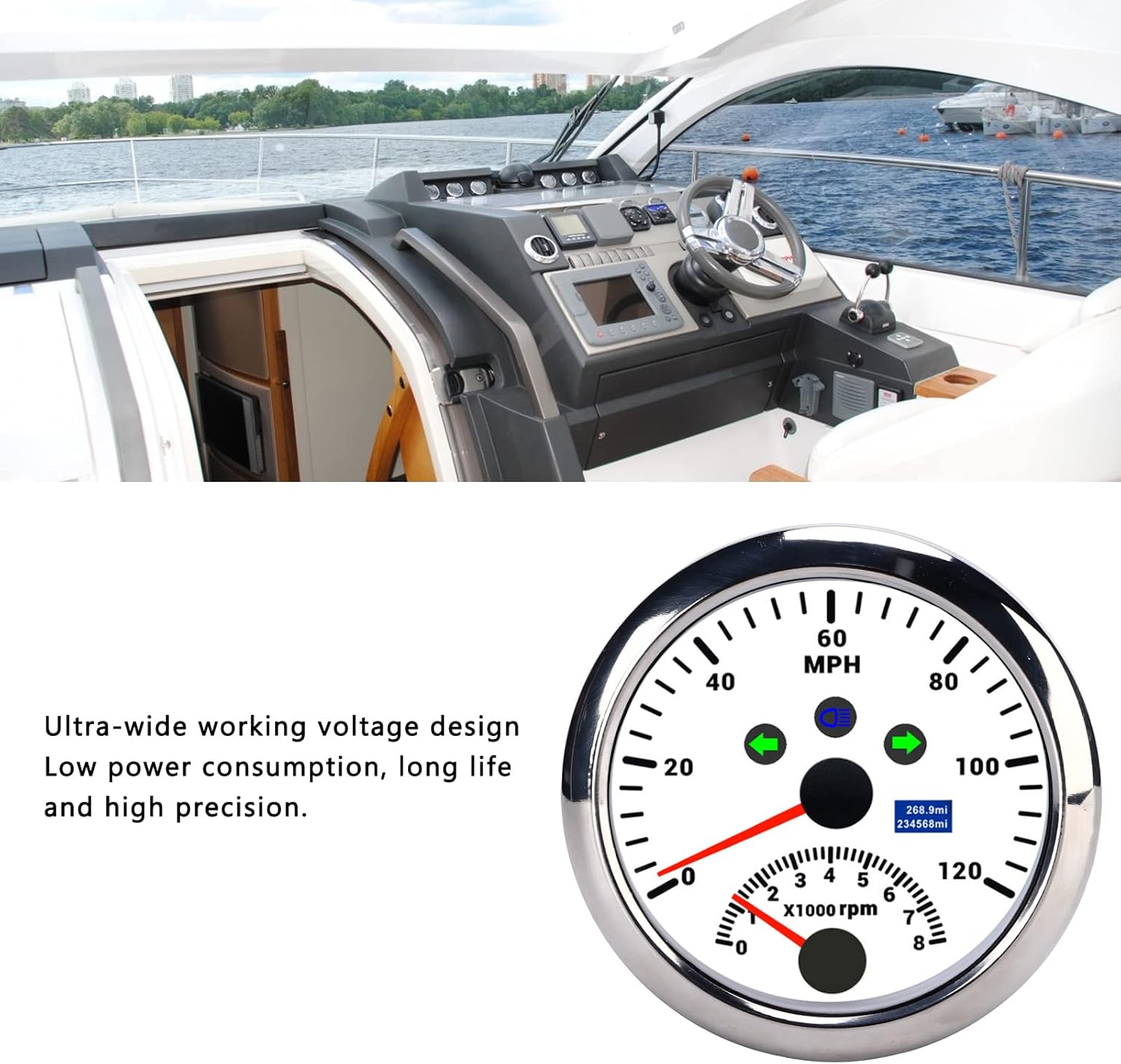
Image 4.1: The gauge highlighting its ultra-wide working voltage design, low power consumption, long life, and high precision.
5. Setup and Installation
Follow these steps carefully to install your GPS Speedometer and Tachometer.
5.1 Mounting the Gauge
- Choose a suitable location on your dashboard or panel for installation.
- Cut an 85mm (3-3/8 inch) diameter hole in the chosen panel.
- Insert the gauge into the hole.
- Secure the gauge using the provided mounting bracket and nuts from the rear.
5.2 Wiring Connections
Refer to the wiring diagram below and the labels on the back of the unit for correct connections.

Image 5.1: Rear view of the gauge with labeled wiring harness.
- Black Wire: Ground (-)
- Red Wire: 9-36V DC Power (+)
- Blue Wire: Backlight (+)
- Yellow Wire: High Beam Signal (+)
- White Wire: Buzzer Alarm (-)
- Brown Wire: Left Turn Signal (+)
- Gray Wire: Right Turn Signal (+)
- Connect the GPS antenna to the designated port on the back of the unit. Ensure the antenna is mounted in a location with a clear view of the sky.
Important: Ensure all connections are secure and properly insulated. Incorrect wiring can damage the unit or vehicle electrical system.
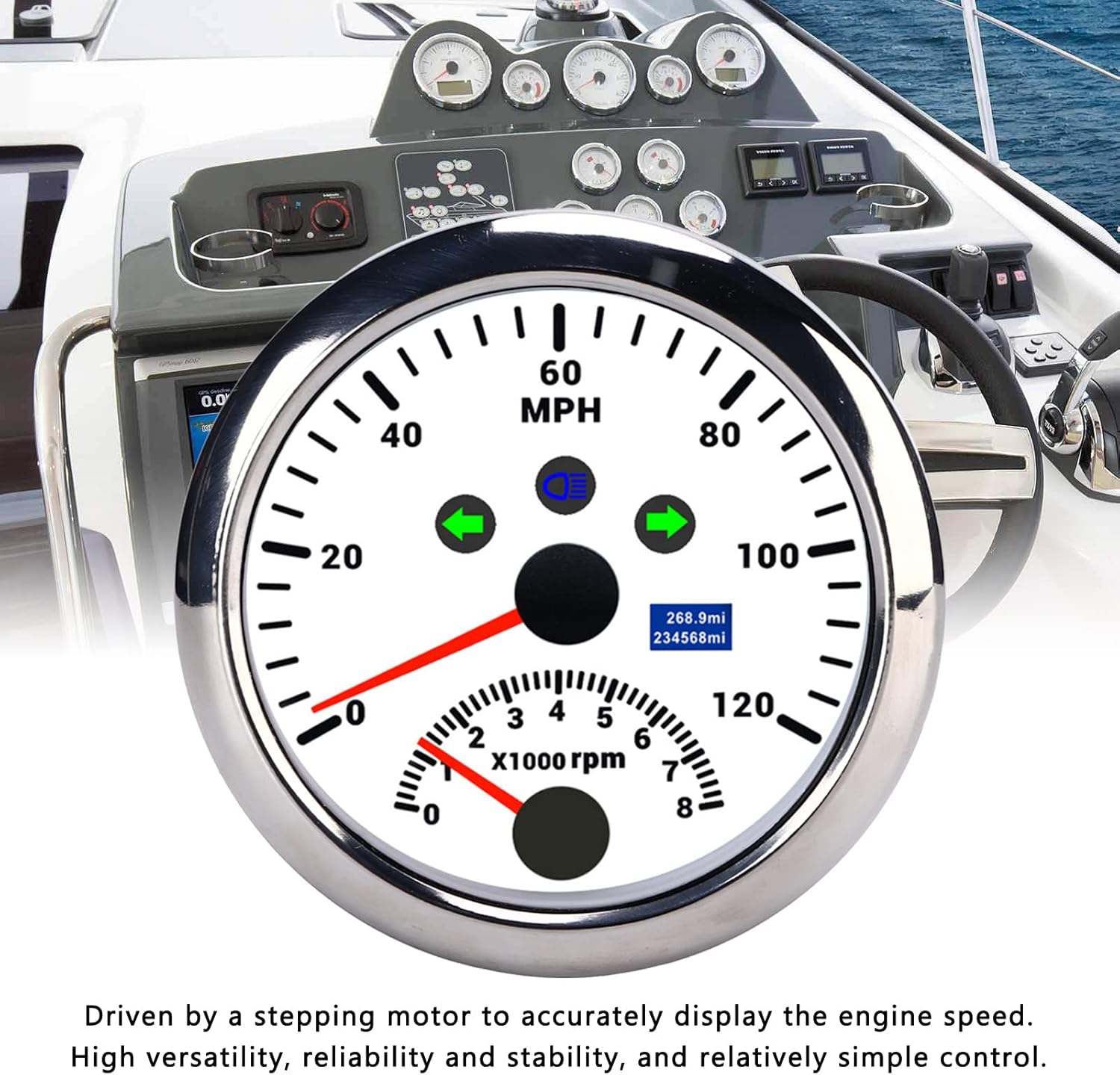
Image 5.2: Example installation of the gauge in a boat dashboard.
6. Operating Instructions
6.1 Power On
Once properly installed and wired, turn on your vehicle's ignition. The gauge will power on, and the LCD display will illuminate. The GPS module will begin searching for satellite signals.
6.2 Speedometer Function
After acquiring a GPS signal, the speedometer needle will indicate your current speed in MPH. The LCD display may show additional information such as trip distance or total mileage.
6.3 Tachometer Function
The tachometer needle will display your engine's RPM (revolutions per minute) based on the signal received from your vehicle's engine.
6.4 Over-Speed Alarm
The unit features an adjustable over-speed buzzer alarm. Consult the detailed instructions in the included user manual (physical copy) for specific steps on how to set or adjust the alarm threshold. When the set speed is exceeded, the buzzer will sound.
6.5 Indicator Lights and Backlight
- The integrated indicator lights for Left Turn, High Beam, and Right Turn will illuminate when their respective signals are active.
- The red backlight for the LCD display and gauge face will activate when the backlight wire is connected to a power source (e.g., vehicle's illumination circuit).

Image 6.1: The gauge with its red backlight illuminated, showing clear visibility in low light conditions.
7. Maintenance
- Cleaning: Use a soft, damp cloth to clean the gauge face. Avoid abrasive cleaners or solvents that could damage the anti-fog curved glass or bezel.
- Connections: Periodically check all wiring connections to ensure they remain secure and free from corrosion, especially in marine environments.
- GPS Antenna: Ensure the GPS antenna remains unobstructed and securely mounted for optimal signal reception.
- Weather Resistance: The unit is IP67 rated for water and dust resistance. While designed for harsh environments, avoid prolonged submersion or direct high-pressure water jets.
8. Troubleshooting
| Problem | Possible Cause | Solution |
|---|---|---|
| Gauge does not power on. | No power supply or incorrect wiring. | Check the red power wire and black ground wire connections. Ensure the vehicle's ignition is on. Verify voltage (9-36V DC). |
| Speedometer not displaying speed or inaccurate. | No GPS signal or antenna issue. | Ensure the GPS antenna is securely connected and has a clear view of the sky. Move to an open area if indoors or under heavy cover. Allow time for signal acquisition. |
| Tachometer not displaying RPM or inaccurate. | Incorrect engine signal connection. | Verify the tachometer signal wire connection to your engine's RPM output. Consult your vehicle's service manual for the correct signal source. |
| Backlight not working. | Backlight wire not connected or faulty. | Check the blue backlight wire connection. Ensure it is receiving power when the vehicle's lights are on. |
| Over-speed alarm not functioning. | Alarm setting incorrect or buzzer wire issue. | Check the white buzzer alarm wire connection. Review the alarm setting procedure in the full user manual to ensure it is configured correctly. |
9. Warranty and Support
Specific warranty information for the NDNCZDHC CX8192 GPS Speedometer and Tachometer is not provided in this document. Please refer to the original product packaging or contact your retailer for details regarding warranty coverage and customer support.
For technical assistance or further inquiries, please contact the manufacturer NDNCZDHC through their official channels or the vendor from whom you purchased the product.