1. Introduction
The JDOUNFMO 622B is a professional smart multimeter designed for accurate and reliable electrical measurements. It features automatic selection of measuring functions and ranges, a high-precision 9999-count VA color LCD, and robust overload protection. This manual provides essential information for the safe and effective use of your 622B multimeter.

Figure 1: JDOUNFMO 622B Smart Multimeter and included accessories.
2. Safety Information
WARNING: To avoid electric shock or personal injury, read and understand all safety information before using this multimeter.
- Always ensure the multimeter is in the correct function and range before making measurements.
- Do not apply voltage or current that exceeds the maximum rated limits for the multimeter. The maximum voltage between the measuring end and ground is 1000V DC or 750V AC.
- Inspect test leads for damaged insulation or exposed metal before use. Replace if damaged.
- Do not use the multimeter if it appears damaged or if the case is open.
- Exercise extreme caution when working with voltages above 30V AC RMS, 42V peak, or 60V DC. These voltages pose a shock hazard.
- Remove test leads from the circuit before changing functions or ranges.
- Replace batteries immediately when the low battery indicator appears to ensure accurate readings.
- Do not operate the multimeter in explosive gas, vapor, or dusty environments.
- Always disconnect power to the circuit and discharge all high-voltage capacitors before measuring resistance, continuity, diodes, or capacitance.
3. Product Overview
3.1 Key Features
- Display: VA Color Large HD LCD Display with 9999 counts.
- Measurement Functions: AC/DC Voltage, AC/DC Current, Resistance, Capacitance, Temperature, Frequency, Duty Cycle, Diode, NCV (Non-Contact Voltage), Live Zero Line detection, Buzzer.
- Ranging: Automatic and Manual selection.
- Special Features: True RMS, Data Hold, Auto Power Off (15 minutes), Low Battery Indication, Laser Pointing Lamp, Flashlight.
- Protection: Overload protection, Silicone protective sheath.
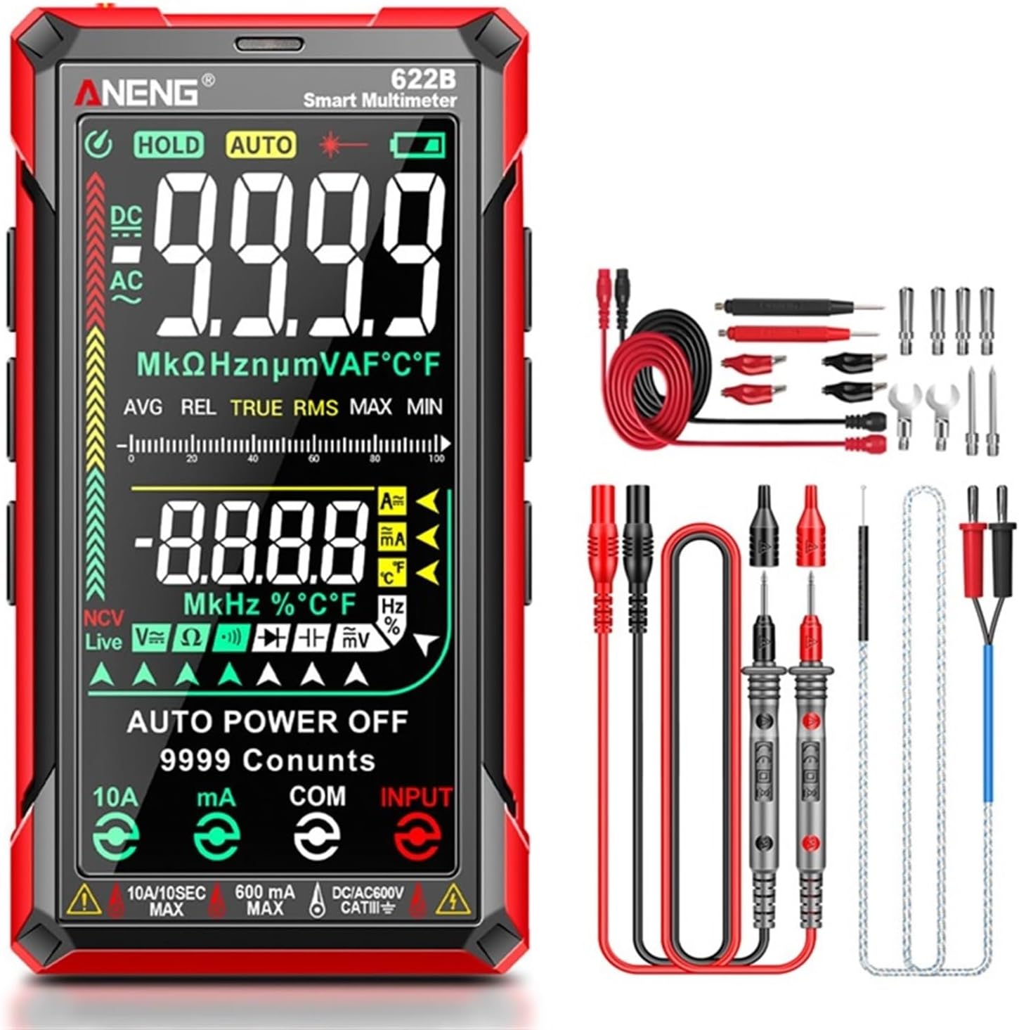
Figure 2: Key features of the 622B Multimeter.
3.2 Components
The JDOUNFMO 622B multimeter consists of the main unit, test leads, and a temperature probe. Key physical components include:
- VA Color LCD Display: Shows measurement readings, function indicators, and battery status.
- Function Buttons: For selecting specific modes or features (e.g., HOLD, AUTO, SEL, NCV, REL, MAX/MIN, Flashlight/Laser).
- Input Jacks:
- 10A/10SEC MAX: For high current measurements (up to 10A).
- 600mA MAX: For milliampere current measurements.
- COM: Common terminal for all measurements.
- INPUT: For voltage, resistance, capacitance, frequency, diode, and temperature measurements.
- Infrared Laser Head: Located at the top for laser positioning.
- Side Silicone Keypad: Provides tactile feedback for button presses.
- Silicone Protection: Anti-falling silicone protective sleeve for durability.
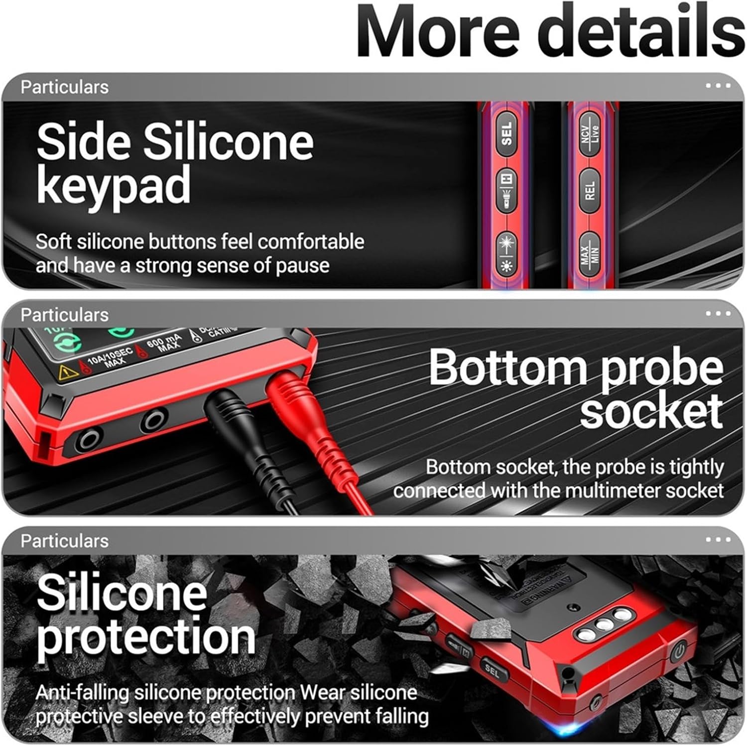
Figure 3: Detailed view of multimeter components.
4. Setup
4.1 Battery Installation
The JDOUNFMO 622B multimeter requires four (4) 1.5V AAA batteries (not included). To install or replace batteries:
- Ensure the multimeter is powered off and all test leads are disconnected.
- Locate the battery compartment cover on the back of the multimeter.
- Use a screwdriver to open the battery compartment.
- Insert four new AAA batteries, observing the correct polarity (+/-) as indicated inside the compartment.
- Replace the battery compartment cover and secure it with the screw.
NOTE: When the low battery indicator appears on the display, replace the batteries promptly to maintain measurement accuracy.
5. Operating Instructions
The 622B multimeter features automatic function and range selection for most measurements. For specific functions, use the 'SEL' button to cycle through modes.
5.1 General Operation
- Power On/Off: Press the power button to turn the multimeter on or off. The device will automatically power off after 15 minutes of inactivity.
- Auto/Manual Ranging: The multimeter defaults to auto-ranging. Press the 'AUTO' button to switch between auto and manual ranging modes if desired.
- Data Hold: Press the 'HOLD' button to freeze the current reading on the display. Press again to release.
- Flashlight/Laser: Press the flashlight/laser button to activate the built-in flashlight or the infrared laser pointer.

Figure 4: Activating the infrared laser for positioning.
5.2 Measuring AC/DC Voltage
- Insert the red test lead into the 'INPUT' jack and the black test lead into the 'COM' jack.
- Turn on the multimeter. It will automatically detect AC or DC voltage.
- Connect the test probes across the circuit or component to be measured.
- Read the voltage value on the display.
5.3 Measuring AC/DC Current
CAUTION: Never connect the multimeter in parallel with a voltage source when measuring current. This can damage the multimeter and the circuit.
- For mA current: Insert the red test lead into the '600mA MAX' jack and the black test lead into the 'COM' jack.
- For 10A current: Insert the red test lead into the '10A/10SEC MAX' jack and the black test lead into the 'COM' jack.
- Break the circuit and connect the multimeter in series with the load.
- Read the current value on the display. The multimeter will automatically detect AC or DC current.
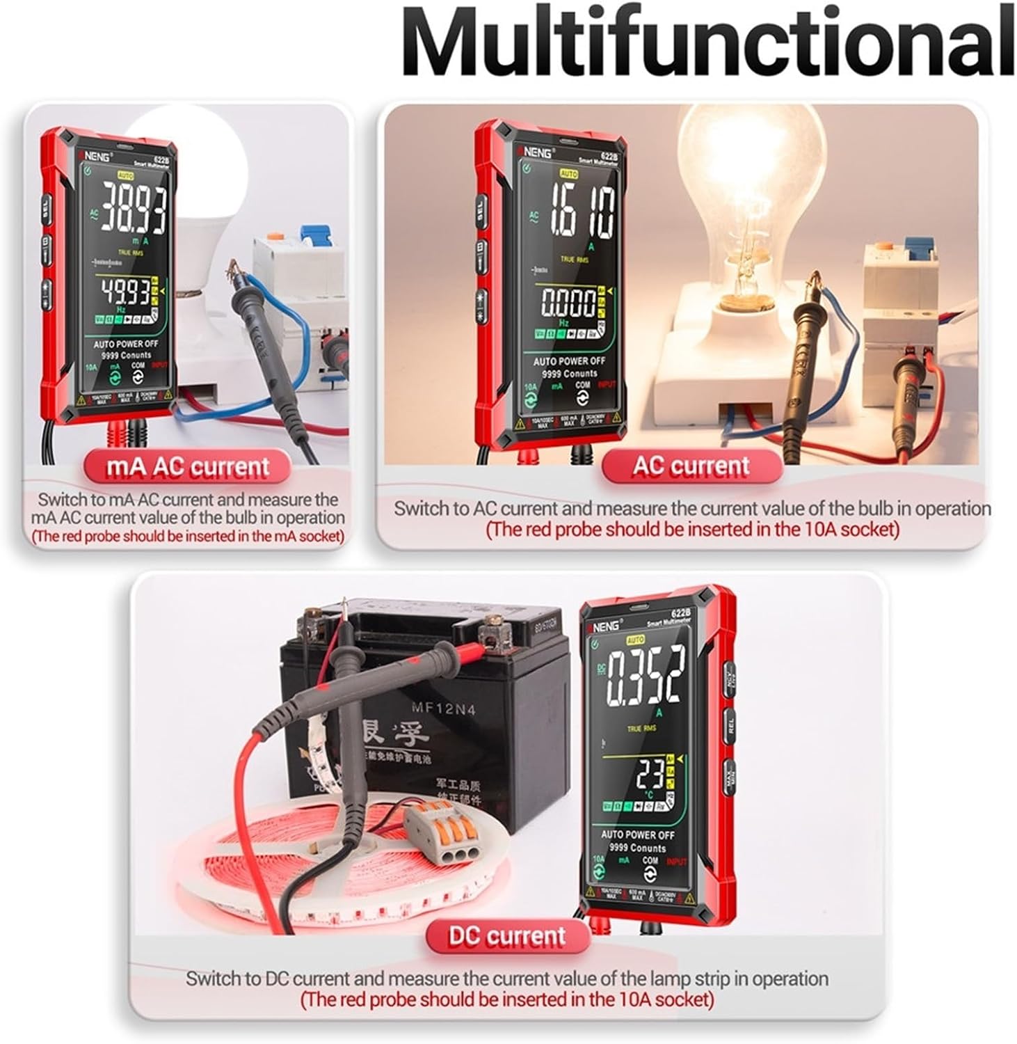
Figure 5: Examples of AC and DC current measurements.
5.4 Measuring Resistance
- Insert the red test lead into the 'INPUT' jack and the black test lead into the 'COM' jack.
- Ensure the circuit is de-energized and all capacitors are discharged.
- Connect the test probes across the component to be measured.
- Read the resistance value on the display.
5.5 Measuring Capacitance
- Insert the red test lead into the 'INPUT' jack and the black test lead into the 'COM' jack.
- Ensure the capacitor is fully discharged before measurement.
- Connect the test probes across the capacitor terminals.
- Read the capacitance value on the display.
5.6 Diode Test
- Insert the red test lead into the 'INPUT' jack and the black test lead into the 'COM' jack.
- Ensure the circuit is de-energized.
- Connect the red probe to the anode and the black probe to the cathode of the diode.
- Read the forward voltage drop. Reverse the probes; the display should show 'OL' for a good diode.
5.7 Temperature Measurement
- Insert the temperature probe into the 'INPUT' and 'COM' jacks, observing polarity if applicable.
- Place the tip of the temperature probe on or near the object whose temperature is to be measured.
- Read the temperature value on the display (in Celsius or Fahrenheit).
5.8 NCV (Non-Contact Voltage) Detection
- Press the 'NCV' button to enter NCV mode.
- Move the top of the multimeter close to the conductor suspected of having AC voltage.
- The multimeter will emit an audible beep and the display will indicate the presence of AC voltage.
5.9 Live Zero Line Detection
- Press the 'LIVE' button to enter Live Zero Line detection mode.
- Use the red test probe to touch the conductor.
- The display will indicate if it is a live wire or a zero line.
6. Maintenance
6.1 Cleaning
Wipe the case with a damp cloth and mild detergent. Do not use abrasives or solvents. Ensure the multimeter is completely dry before use.
6.2 Battery Replacement
Refer to Section 4.1 for battery replacement instructions. Always use fresh AAA batteries and dispose of old batteries responsibly.
6.3 Test Lead Care
Regularly inspect test leads for any signs of damage, such as cracked insulation or exposed metal. Replace damaged leads immediately to prevent electric shock.
7. Troubleshooting
- Display shows 'OL' (Overload): The measured value exceeds the selected range. In auto-ranging mode, this indicates the value is beyond the multimeter's maximum capability for that function.
- No display or faint display: Check battery installation and replace batteries if necessary.
- Inaccurate readings: Ensure test leads are properly connected, batteries are fresh, and the correct function/range is selected. Environmental factors can also affect accuracy.
- Multimeter does not turn on: Check battery polarity and ensure batteries are not depleted.
8. Specifications

Figure 6: Detailed function, range, and accuracy specifications.
| Parameter | Value |
|---|---|
| Display | 9999 Counts VA Color LCD |
| Ranging | Auto/Manual |
| Material | ABS+TPE |
| True RMS | Yes |
| Laser Pointing Lamp | Yes |
| Data Hold | Yes |
| Auto Power Off | 15 minutes |
| Low Battery Indication | Yes |
| Sampling Time | Approx. 3 times/second |
| Power Supply | 4 x 1.5V AAA batteries (not included) |
| Weight | 1.76 ounces (50g) - Note: Product description states 210g, Amazon spec states 1.76oz. Please refer to product packaging for accurate weight. |
| Max Voltage (Input to Ground) | 1000V DC or 750V AC |
| Function | Range | Accuracy |
|---|---|---|
| AC Current | 60.00mA/600.0mA/6.000A/10.00A | ±(1.0% reading + 8 digits) |
| DC Current | 60.00mA/600.0mA/6.000A/10.00A | ±(1.0% reading + 5 digits) |
| AC Voltage | 600.0mV/9.999V/99.99V/750.0V | ±(0.8% reading + 5 digits) |
| DC Voltage | 600.0mV/9.999V/99.99V/999.9V | ±(0.5% reading + 3 digits) |
| Resistance | 999.9Ω/9.999KΩ/99.99KΩ/999.9KΩ/9.999MΩ/99.99MΩ | ±(0.8% reading + 3 digits) |
| Capacitance | 9.999nF/999.9nF/9.999uF/99.99uF/999.9uF/9.999mF/99.99mF | ±(10% reading + 40 digits) for 9.999nF; ±(2.5% reading + 20 digits) for others |
| Temperature | -40~1000°C / -40~1832°F | ±(1% reading + 3°C/°F) |
| Frequency | 10Hz/100Hz/1000Hz/10KHz/100KHz/1000KHz/10MHz | ±(1.0% reading + 5 digits) for 10Hz-1000KHz; ±(3.0% reading + 5 digits) for 10MHz |
| Duty Cycle | 1~99% | ±(3.0% reading + 3 digits) |
| Diode | 1V | 0.001V resolution |
9. Warranty & Support
For warranty information and technical support regarding your JDOUNFMO 622B Smart Multimeter, please refer to the documentation included with your purchase or contact the manufacturer directly. Keep your purchase receipt as proof of purchase for any warranty claims.
Manufacturer: JDOUNFMO