1. Introduction
This manual provides detailed instructions for the proper setup, operation, and maintenance of your K&F CONCEPT Mini Desktop Tripod, Model S225A1+BH-25. Please read this manual thoroughly before using the product to ensure optimal performance and longevity.
The K&F CONCEPT Mini Desktop Tripod is a compact and portable support system designed for cameras, camcorders, projectors, and smartphones. It features a 360-degree ball head, quick-release plate, and adjustable legs for versatile shooting angles.
2. Product Overview
Familiarize yourself with the components of your K&F CONCEPT Mini Desktop Tripod.
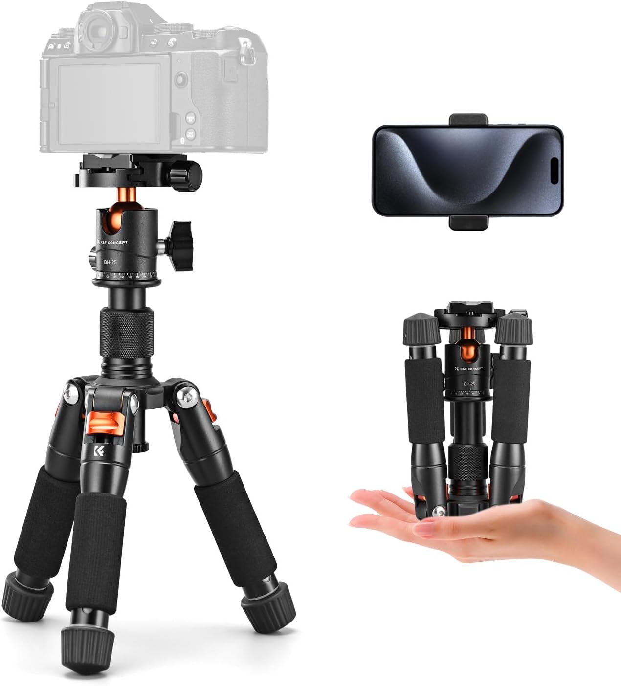
Image 2.1: K&F CONCEPT Mini Desktop Tripod with accessories.
The tripod is designed for portability, with a reverse folding design that allows it to be stored compactly.

Image 2.2: The tripod's compact size for easy transport.
Key components include:
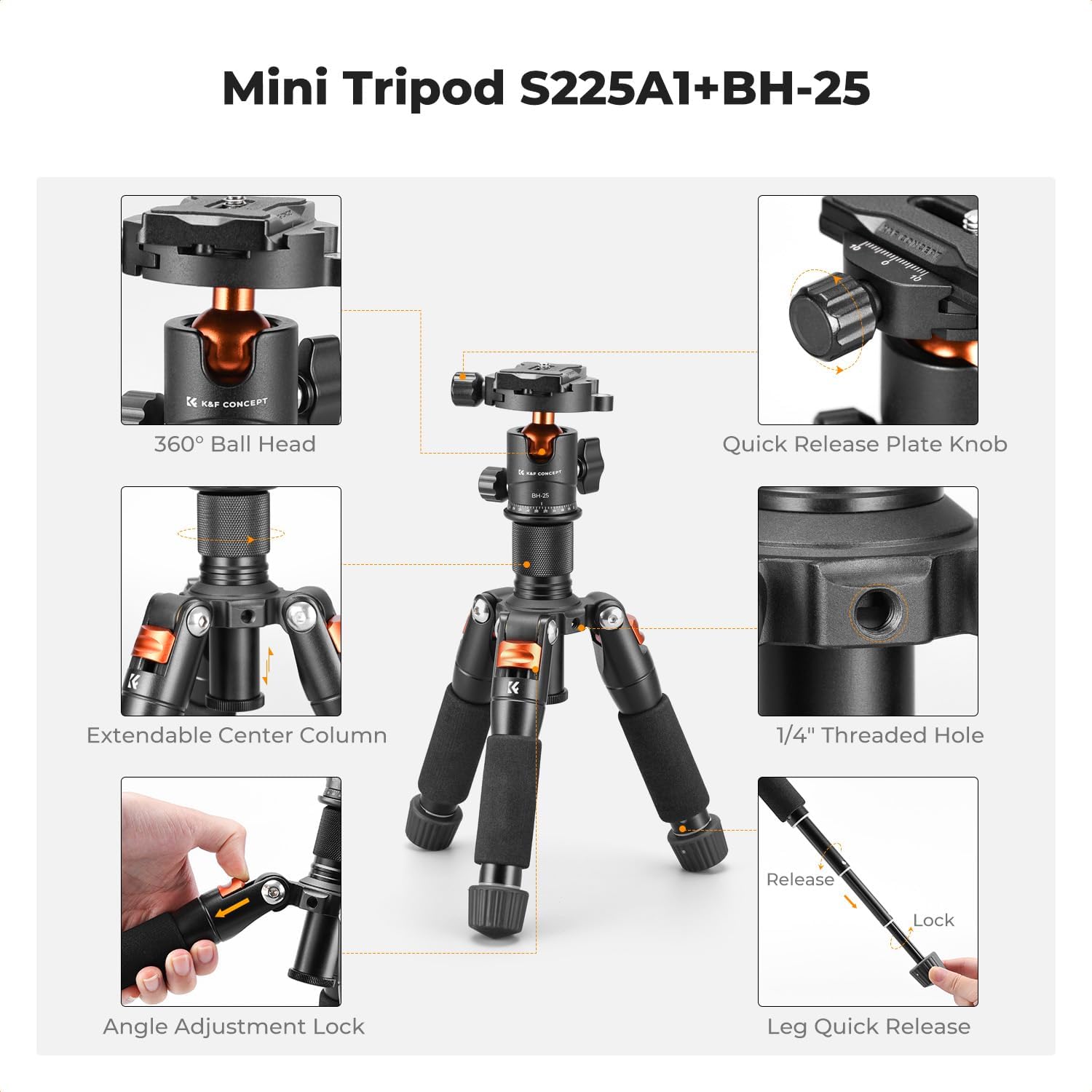
Image 2.3: Detailed view of tripod components.
- 360° Ball Head: Allows for flexible camera positioning.
- Quick Release Plate Knob: Secures and releases the quick release plate.
- Extendable Center Column: Provides additional height adjustment and supports low-angle shooting when reversed.
- 1/4" Threaded Hole: For attaching external accessories like microphones or fill lights.
- Angle Adjustment Lock: Adjusts the spread of the tripod legs.
- Leg Quick Release: Mechanism for extending and retracting leg sections.
3. Setup
3.1 Unfolding the Tripod
- Gently unfold the tripod legs until they are fully extended.
- Adjust the leg angles as needed (refer to Section 4.4).
3.2 Attaching the Quick Release Plate to Your Device
- Locate the quick release plate on the ball head.
- Unscrew the quick release plate knob to detach the plate from the ball head.
- Securely attach the quick release plate to the 1/4-inch tripod socket on your camera, camcorder, or smartphone holder. Ensure it is tightened firmly to prevent rotation.
3.3 Mounting Your Device to the Tripod
- With the quick release plate attached to your device, align the plate with the receiver on the ball head.
- Slide the plate into the receiver until it clicks into place.
- Tighten the quick release plate knob to secure your device firmly to the tripod.
4. Operating Instructions
4.1 Leg Adjustment
The tripod features 5-section legs for flexible height adjustment. Each leg section can be adjusted independently.
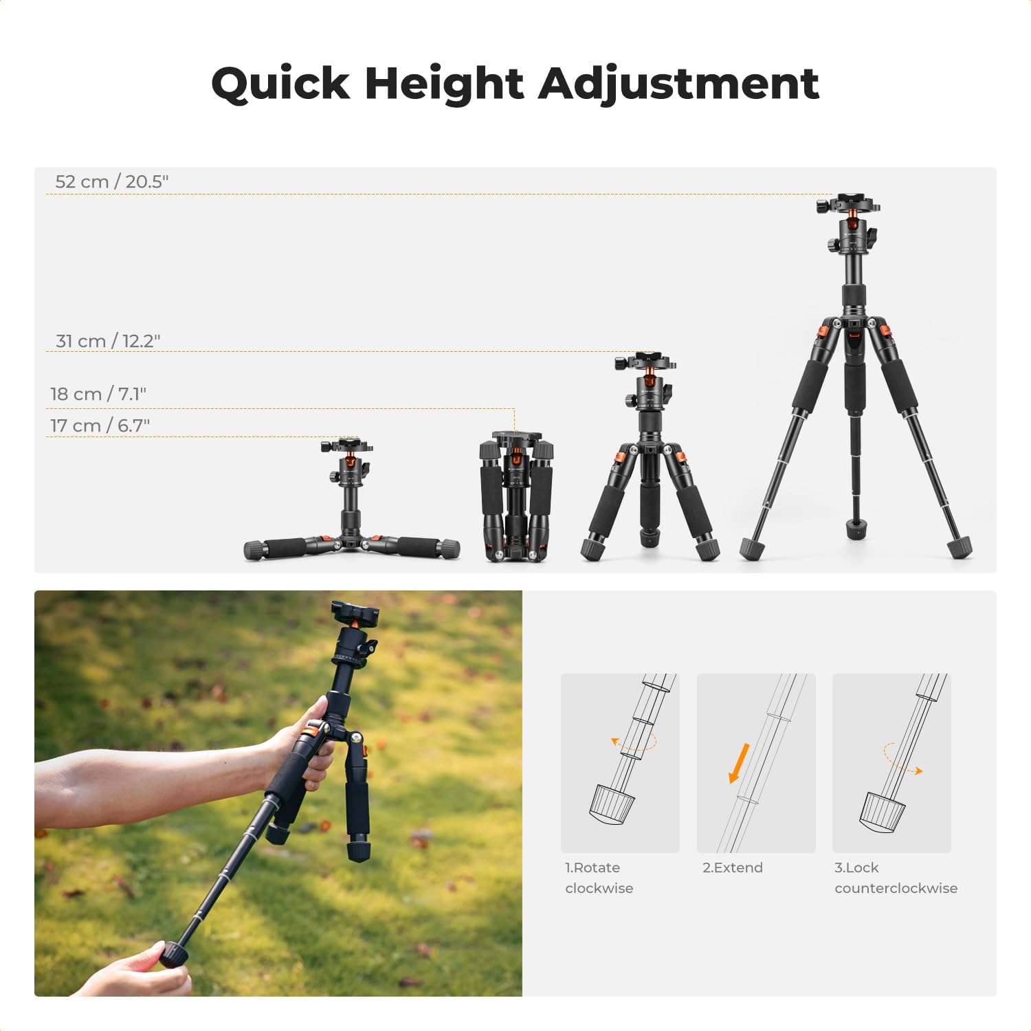
Image 4.1: Leg extension and height options.
- To extend a leg section, rotate the leg quick release mechanism counter-clockwise to unlock.
- Pull the leg section outwards to the desired length.
- Rotate the leg quick release mechanism clockwise to lock the section in place.
- Repeat for all desired leg sections and legs to achieve the required height. The maximum height is 52 cm (20.5 inches).
4.2 Center Column Adjustment
The center column can be extended or retracted to fine-tune the tripod's height. It can also be inverted for low-angle photography.
- To extend the center column, loosen the center column locking knob.
- Pull the center column upwards to the desired height.
- Tighten the center column locking knob to secure it.
- For low-angle shooting, fully extend and remove the center column, then re-insert it upside down into the tripod base. Secure with the locking knob.
4.3 Ball Head Operation
The integrated ball head provides precise control over camera positioning.
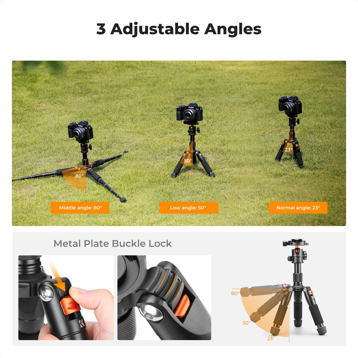
Image 4.2: Ball head controls and movement.
- 360° Pan: Loosen the 360° pan lock knob to rotate the camera horizontally. Tighten to secure.
- 90° Tilt: Loosen the 90° tilt lock knob to adjust the camera's vertical angle. Tighten to secure.
- Quick Release Plate Knob: Used for attaching and detaching your device (refer to Section 3.2 and 3.3).
4.4 Angle Adjustment
The tripod legs can be set to three distinct angles to adapt to various terrains and shooting requirements.
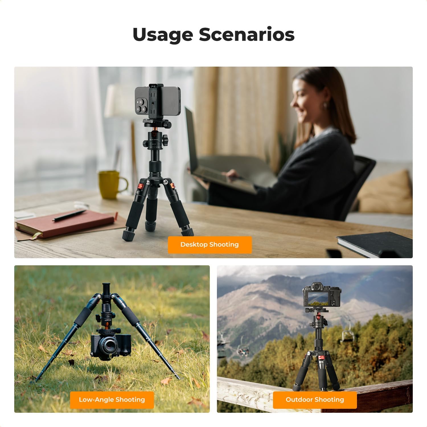
Image 4.3: Adjustable leg angles for versatile shooting.
- To change a leg angle, press the angle adjustment lock (metal plate buckle lock) located at the top of each leg.
- Move the leg to one of the predefined angle positions: 23° (Normal), 50° (Low), or 80° (Middle).
- Release the lock to secure the leg in the chosen angle.
4.5 Expanding Interfaces
The tripod includes a 1/4" threaded hole for attaching additional accessories.
Image 4.4: 1/4" threaded hole for accessory expansion.
This threaded hole allows for the attachment of various compatible accessories such as microphones, LED lights, or monitors, enhancing your shooting setup.
5. Maintenance
- Cleaning: Wipe the tripod with a soft, dry cloth after each use to remove dust and dirt. For stubborn grime, use a slightly damp cloth and mild soap, then dry thoroughly.
- Lubrication: Avoid applying lubricants to the leg locking mechanisms or ball head, as this can attract dust and impair function.
- Storage: Store the tripod in a dry, cool place, away from direct sunlight and extreme temperatures.
- Inspection: Periodically check all screws and knobs to ensure they are tight. Do not overtighten.
6. Troubleshooting
6.1 Center Column Adjustment Issues
If the center column adjustment knob becomes difficult to thread or re-engage after being fully unscrewed:
- Unscrew the limiter plug located at the bottom of the center column.
- Carefully pull the center column out from the tripod base.
- Re-engage the adjustment knob onto the center column threads gently. Do not fully tighten yet.
- Insert the center column back into its socket. If it does not fit, slightly loosen the adjustment knob.
- Once the column is in place, tighten the adjustment knob to secure it at the desired height.
- Reinstall the limiter plug at the bottom of the center column.
6.2 Tripod Instability
- Ensure all leg sections are fully extended and their quick release mechanisms are securely locked.
- Verify that the quick release plate knob is tightly secured to your device and the device is firmly seated on the ball head.
- Check that the leg angle adjustment locks are engaged for all three legs.
- Ensure the tripod is placed on a stable, level surface.
7. Specifications
| Feature | Specification |
|---|---|
| Model | S225A1+BH-25 |
| Material | Aluminum Alloy |
| Maximum Height | 52 cm (20.5 inches) |
| Minimum Height | 17 cm (6.7 inches) |
| Folded Height | 18 cm (7.1 inches) |
| Net Weight | 0.7 kg (1.54 lbs) |
| Load Capacity | 6 kg (13.2 lbs) |
| Leg Sections | 5 |
| Head Type | Ball Head |
| Head Interface | 1/4" Screw |
| Compatible Devices | Camcorder, Camera, Projector, Smartphone |
8. What's in the Box
- K&F Concept Camera Tripod x1
- Cellphone Holder x1
- Quick Release Plate x1
9. Warranty and Support
For warranty information and customer support, please refer to the documentation included with your purchase or contact K&F CONCEPT directly through their official website or authorized retailers. Keep your proof of purchase for warranty claims.