1. Introduction
This manual provides detailed instructions for the safe and efficient installation, operation, and maintenance of the HVGZDQQD SSR-DA41F Solid State Relay Module. Please read this manual thoroughly before using the product to ensure proper functionality and to prevent damage or injury.
2. Safety Information
Always observe the following safety precautions to prevent electric shock, fire, or damage to the product and connected equipment:
- Ensure all power sources are disconnected before installation, wiring, or maintenance.
- Installation and wiring should only be performed by qualified personnel.
- Do not exceed the specified voltage and current ratings.
- Protect the relay from moisture, dust, and extreme temperatures.
- Verify correct polarity for DC control input.
- Use appropriate heat sinking for high current applications to prevent overheating.
3. Product Overview
The HVGZDQQD SSR-DA41F is a DC-controlled AC solid state relay designed for reliable switching of AC loads. It features a compact design and is suitable for various industrial control applications.
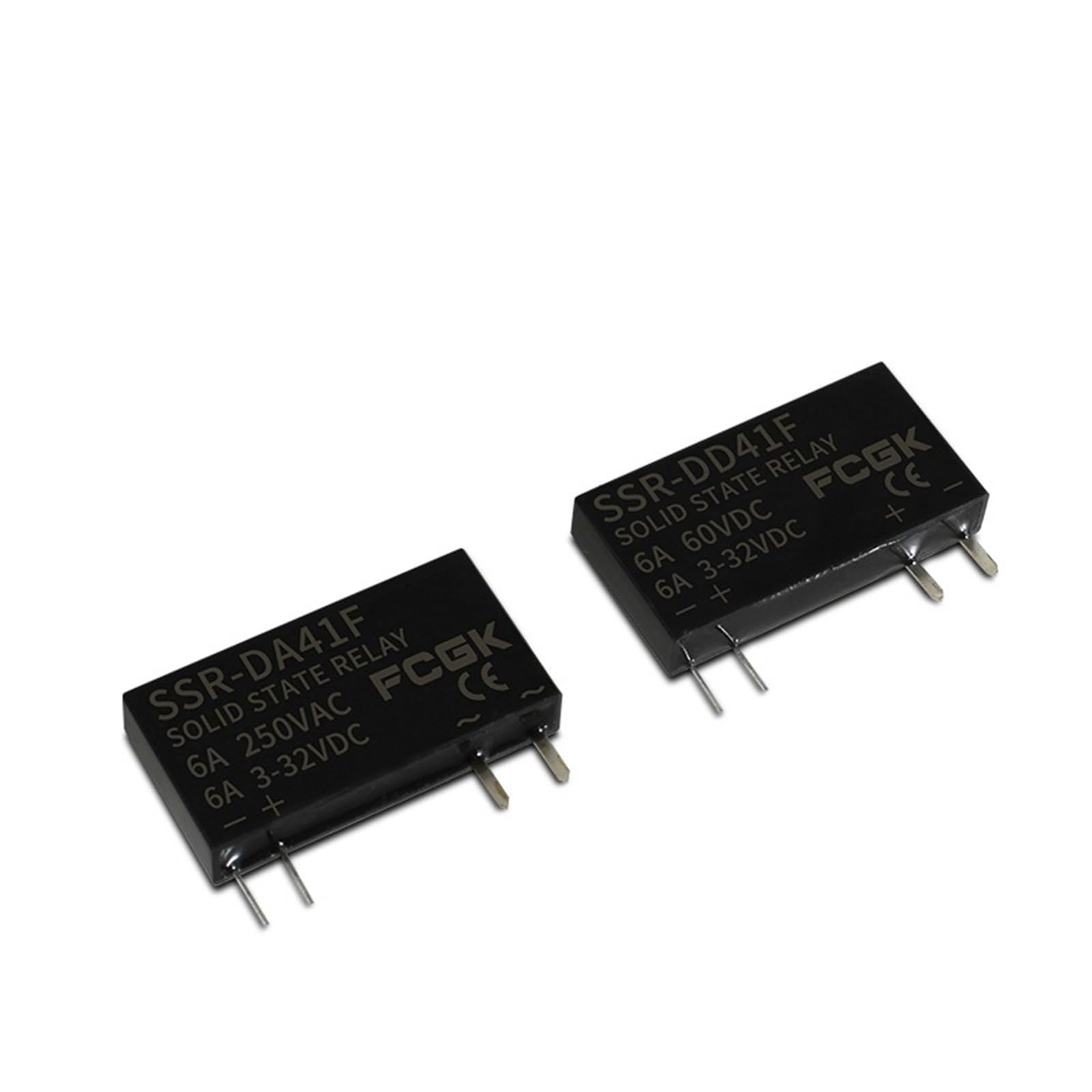
Figure 3.1: Angled view of the SSR-DA41F Solid State Relay Module, showing input and output terminals and product labeling.

Figure 3.2: Front view of the SSR-DA41F, displaying the model number, "SOLID STATE RELAY", "6A 250VAC", and "6A 3-32VDC" ratings, along with input polarity markings.
Key Features:
- DC control input (3-32VDC)
- AC load switching (up to 250VAC, 6A)
- Compact and reliable solid-state design
- No moving parts for extended lifespan
4. Specifications
| Parameter | Value |
|---|---|
| Model | SSR-DA41F |
| Control Voltage | 3-32VDC |
| Load Voltage | 250VAC |
| Load Current | 6A |
| Brand | HVGZDQQD |
| Item Weight | 200 Grams |
| ASIN | B0DCSQVQGT |
5. Setup and Installation
Follow these steps for proper installation of the SSR-DA41F module:
- Mounting: Securely mount the SSR-DA41F in a suitable enclosure or panel. For applications involving currents close to the maximum rating, consider mounting the relay on a heat sink to dissipate heat effectively.
- Control Input Wiring (DC):
- Connect the positive (+) terminal of your DC control signal (3-32VDC) to the '+' input terminal of the SSR.
- Connect the negative (-) terminal of your DC control signal to the '-' input terminal of the SSR.
- Ensure correct polarity to prevent damage.
- Load Output Wiring (AC):
- Connect one terminal of the AC load (e.g., motor, heater) to one of the AC output terminals (marked with '~') of the SSR.
- Connect the other AC output terminal of the SSR to one side of the AC power source (e.g., Live or Neutral).
- Connect the other side of the AC load to the remaining side of the AC power source.
- Ensure the load voltage and current do not exceed the SSR's ratings (250VAC, 6A).
- Verification: Double-check all wiring connections for tightness and correctness before applying power.

Figure 5.1: Bottom view of the SSR-DA41F, illustrating the pin configuration for control input and load output connections.
6. Operating Instructions
Once properly installed and wired, the SSR-DA41F operates as follows:
- Control Signal Application: When a DC control voltage between 3V and 32V is applied to the input terminals (+ and -), the internal circuitry of the SSR will activate.
- Load Switching: Upon activation, the SSR will switch on, allowing AC current to flow through the load connected to its output terminals.
- Control Signal Removal: When the DC control voltage is removed or drops below the threshold, the SSR will switch off, interrupting the AC current to the load.
- Indicator: Some SSR models may include an LED indicator that illuminates when the control signal is applied and the relay is active.
The SSR-DA41F is designed for zero-cross switching, meaning it turns on when the AC voltage crosses zero, which helps reduce electrical noise and extends the life of the load.
7. Maintenance
The SSR-DA41F is a solid-state device with no moving parts, requiring minimal maintenance. However, periodic checks are recommended:
- Visual Inspection: Regularly inspect the relay and its connections for any signs of damage, discoloration, or loose wiring.
- Cleanliness: Keep the relay free from dust and debris. Use a soft, dry cloth for cleaning. Do not use liquid cleaners.
- Temperature: Ensure the operating environment temperature remains within the specified range and that adequate ventilation or heat sinking is provided, especially during continuous high-current operation.
8. Troubleshooting
| Problem | Possible Cause | Solution |
|---|---|---|
| SSR does not turn on (load remains off) |
|
|
| SSR does not turn off (load remains on) |
|
|
| SSR overheats |
|
|
9. Warranty and Support
For warranty information or technical support regarding your HVGZDQQD SSR-DA41F Solid State Relay Module, please refer to the product packaging or contact your point of purchase. Keep your purchase receipt as proof of purchase.