1. Introduction
The YXJPP 2C53P is a versatile 3-in-1 digital instrument combining a dual-channel 50MHz digital oscilloscope, a high-precision multimeter, and a signal generator. Featuring a 4.3-inch touchable IPS color screen and a 4000mAh lithium battery, this device is designed for efficient and accurate electrical testing and measurement in various applications.
2. Package Contents
Carefully unpack the device and verify that all items listed below are present and in good condition. If any item is missing or damaged, please contact customer support.
- 1 x 2C53P Digital Oscilloscope
- 1 x Alligator Clip Probe
- 2 x P6100 Oscilloscope Probes
- 1 x Product Manual
- 1 x Multimeter Probe Set
- 1 x USB Data Cable

This image displays the complete package contents of the YXJPP 2C53P Digital Oscilloscope. Numbered items include: 1. 2C53P Oscilloscope, 2. Alligator clip probe, 3. P6100 probes (x2), 4. Product manual, 5. Multimeter probe, 6. Data cable.
3. Product Overview
3.1 Key Features
- 3-in-1 Functionality: Digital Oscilloscope, Multimeter, and Signal Generator.
- Oscilloscope: 2 Channels, 50MHz Bandwidth, 20MHz Bandwidth Limit for precise signal analysis.
- Multimeter: 19999 Count, High Precision, supports ACV, DCV, AC, DC, Capacitance, Resistance, Diode, Continuity, and Temperature measurements.
- Display: 4.3-inch Touchable IPS Color Screen (480*272 pixels) for intuitive waveform exploration and data visualization.
- Power: Integrated 4000mAh Lithium Battery for extended portable use.
- Performance: Utilizes a powerful FPGA+MCU+ADC system for excellent performance.
- Language Support: 8 languages supported for user interface.
3.2 Device Layout and Ports

This image shows the front panel of the YXJPP 2C53P Digital Oscilloscope, highlighting the 4.3-inch IPS touchscreen and control buttons: MENU, RUN, AUTO, and FUNCTION.
The front panel features the 4.3-inch IPS touchscreen display for waveform and measurement data. Below the screen are four primary control buttons:
- MENU: Accesses system settings and various function menus.
- RUN/STOP: Starts or pauses waveform acquisition.
- AUTO: Automatically adjusts oscilloscope settings for optimal waveform display.
- FUNCTION: Switches between different instrument modes (Oscilloscope, Multimeter, Signal Generator).
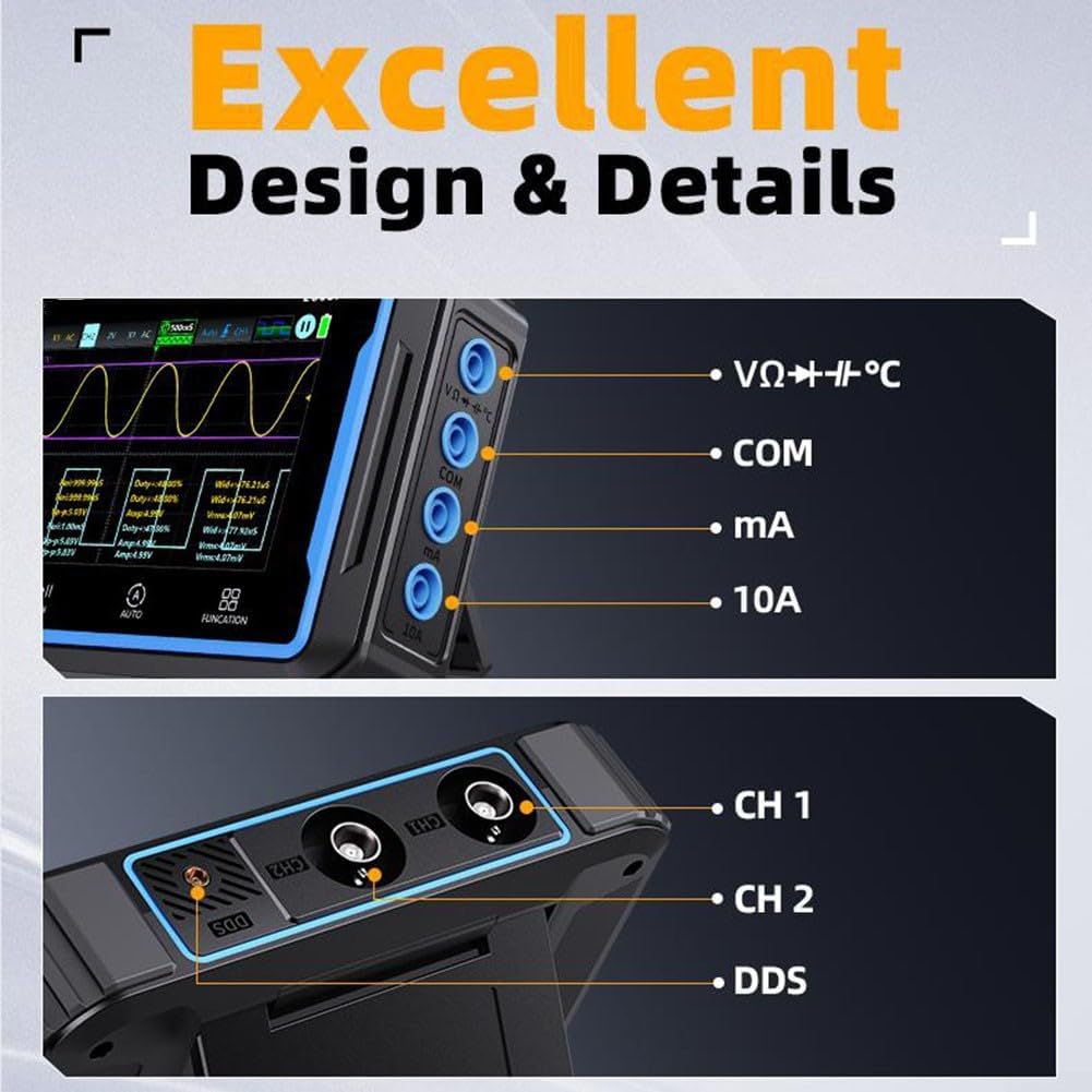
This image details the input and output ports on the YXJPP 2C53P Digital Oscilloscope. On the left, multimeter input jacks are labeled VΩ+Hz/°C, COM, mA, and 10A. On the right, oscilloscope channels CH1, CH2, and a DDS (Direct Digital Synthesis) output port are visible.
The side panels of the device house the input and output ports:
- Multimeter Input Jacks: Labeled VΩ+Hz/°C, COM, mA, and 10A for various multimeter measurements.
- Oscilloscope Channels: CH1 and CH2 BNC connectors for oscilloscope probes.
- DDS Output: A dedicated port for the Direct Digital Synthesis (signal generator) function.
- USB Port: For charging and data transfer to a PC.
4. Setup
4.1 Charging the Device
Before initial use, fully charge the internal 4000mAh lithium battery. Connect the provided USB data cable to the device's USB port and a standard USB power adapter (not included) or a computer's USB port. The charging indicator on the device will show the charging status.
4.2 Connecting Probes
- Oscilloscope Probes (P6100): Connect the BNC connector of the P6100 probes to the CH1 or CH2 BNC input jacks on the device. Ensure a secure connection.
- Multimeter Probes: Insert the red multimeter probe into the VΩ+Hz/°C or 10A jack (depending on the measurement) and the black probe into the COM jack.
- Alligator Clip Probe: This probe can be used for specific applications requiring a secure, hands-free connection, typically with the multimeter function or for grounding.
4.3 Powering On/Off
Press and hold the power button (usually located on the side or top) for a few seconds to turn the device on or off. The IPS screen will illuminate upon successful power-on.
5. Operating Instructions
5.1 Oscilloscope Mode
To enter Oscilloscope mode, press the FUNCTION button until the oscilloscope interface is displayed. The 4.3-inch touchscreen allows for intuitive interaction:
- Waveform Navigation: Use touch gestures to move and zoom in/out on waveforms.
- Auto Setup: Press the AUTO button for automatic adjustment of vertical, horizontal, and trigger settings to display a stable waveform.
- Manual Adjustments: Access the MENU to manually adjust parameters such as vertical scale (Volts/Div), horizontal scale (Time/Div), trigger level, and coupling (AC/DC).
- Bandwidth Limit: The device supports a 20MHz bandwidth limit, useful for filtering out high-frequency noise when measuring lower-frequency signals, such as power supply ripple.

This image illustrates the application of the oscilloscope for measuring power supply ripple, showing a typical ripple waveform on the screen.

This image demonstrates the data visualization capabilities of the oscilloscope, showing how to save up to 5 measurement parameters and check Max/Min value change trends on the display.
5.2 Multimeter Mode
To switch to Multimeter mode, press the FUNCTION button until the multimeter interface is displayed. Connect the multimeter probes to the appropriate jacks based on the desired measurement:
- Voltage (ACV/DCV): Connect probes to VΩ+Hz/°C and COM. Select ACV or DCV from the menu.
- Current (AC/DC): For mA range, connect to mA and COM. For 10A range, connect to 10A and COM. Select AC or DC current.
- Resistance (Ω): Connect probes to VΩ+Hz/°C and COM.
- Capacitance (F): Connect probes to VΩ+Hz/°C and COM.
- Diode Test: Connect probes to VΩ+Hz/°C and COM.
- Continuity Test: Connect probes to VΩ+Hz/°C and COM. An audible beep indicates continuity.
- Temperature (Temp): Use a compatible temperature probe (not included) connected to VΩ+Hz/°C and COM.
The 19999 count display provides high precision for all measurements.

This image highlights the 19999 count high-precision multimeter function, showing the device connected to a circuit for current measurement.

This image displays various multimeter measurement examples, including DC voltage, AC voltage, high current, and low current readings on the device screen.
5.3 Signal Generator (DDS) Mode
To access the Signal Generator mode, press the FUNCTION button until the DDS interface is displayed. Connect a cable to the DDS output port. From the menu, you can configure various waveform types (e.g., sine, square, triangle), frequency, amplitude, and offset. Refer to the on-screen prompts for specific parameter adjustments.
5.4 Data Transfer
The device supports connecting to a PC for viewing or exporting captured data and images.
- Connect the device to your computer using the provided USB data cable.
- On the device, navigate to the USB sharing option (usually found in the system settings menu).
- Enable "USB Sharing" to allow the computer to recognize the device as a storage medium.
- You can then access stored images or data files directly from your computer.
This image shows the process of connecting the oscilloscope to a PC via USB for data sharing, allowing users to view or export captured images.
6. Maintenance
- Cleaning: Use a soft, dry cloth to clean the device. For stubborn dirt, a slightly damp cloth with mild detergent can be used, ensuring no liquid enters the ports or screen edges. Do not use abrasive cleaners or solvents.
- Battery Care: To prolong battery life, avoid fully discharging the battery frequently. If storing the device for an extended period, charge it to approximately 50-70% and recharge every few months.
- Storage: Store the device in a cool, dry place away from direct sunlight, extreme temperatures, and high humidity. Keep it away from strong magnetic fields.
- Probe Care: Handle probes carefully. Avoid bending or stressing the cables excessively. Store probes properly to prevent damage to tips and connectors.
7. Troubleshooting
- Device does not power on: Ensure the battery is charged. Connect the USB cable to a power source and try again.
- No waveform displayed in Oscilloscope mode: Check probe connections. Ensure the input signal is within the device's measurement range. Try pressing the AUTO button. Adjust vertical and horizontal scales.
- Incorrect multimeter readings: Verify probe connections to the correct jacks for the desired measurement type. Ensure the correct measurement function is selected. Check the battery level.
- Screen unresponsive: Try restarting the device. If the issue persists, contact customer support.
- Cannot connect to PC: Ensure the USB cable is properly connected. Verify that "USB Sharing" is enabled on the device. Try a different USB port on your computer.
8. Specifications
| Parameter | Value |
|---|---|
| Model | 2C53P |
| Display | 4.3-inch Touchable IPS Color Screen (480*272 pixels) |
| Oscilloscope Channels | 2CH |
| Oscilloscope Bandwidth | 50MHz |
| Bandwidth Limit | 20MHz |
| Multimeter Count | 19999 |
| Battery | 4000mAh Lithium Battery |
| Supported Languages | 8 |
| Material | Plastic |
9. Warranty and Support
This product comes with a standard manufacturer's warranty. Please refer to the warranty card included in your package or contact your retailer for specific warranty terms and conditions. For technical support, troubleshooting assistance, or inquiries about replacement parts, please contact YXJPP customer service through the contact information provided with your purchase or on the official YXJPP website.