1. Introduction
This manual provides essential information for the safe and effective operation of your YXJPP HO102-100M Handheld Digital Oscilloscope. This device integrates a digital oscilloscope, a multimeter, and a waveform generator into a compact, portable unit, designed for various electrical testing and measurement applications. Please read this manual thoroughly before using the instrument and keep it for future reference.
2. Safety Information
To ensure safe operation and prevent damage to the instrument or injury to yourself, observe the following safety precautions:
- Always use the correct voltage range and input terminals for your measurements.
- Do not apply voltage or current that exceeds the maximum ratings specified for the instrument.
- Inspect test leads and probes for damage before each use. Replace any damaged accessories.
- Do not operate the instrument in wet or damp conditions.
- Ensure the instrument is turned off before connecting or disconnecting test leads, especially when measuring high voltages or currents.
- Refer to the specifications section for detailed input limits.
3. Product Overview
The YXJPP HO102-100M is a versatile handheld device featuring a 3.5-inch HD LED display for clear waveform visualization. Its compact design makes it suitable for fieldwork and educational purposes.
3.1 Key Features
- TFT True Color Display for clear and stable waveform display.
- Mini and portable design for easy handling and transport.
- Dual-channel oscilloscope with 100MHz bandwidth.
- Max Waveform Capture Rate: 1,000,000wfm/s.
- Real-time sampling rate: 250MSa/s (Single CH), 125MSa/s (Dual CH).
- Automatic measurement functions.
- One-click storage.
- Integrated Multimeter with True RMS.
- Waveform Generator output.
3.2 Device Layout and Controls
Familiarize yourself with the device's physical layout and controls as shown below:
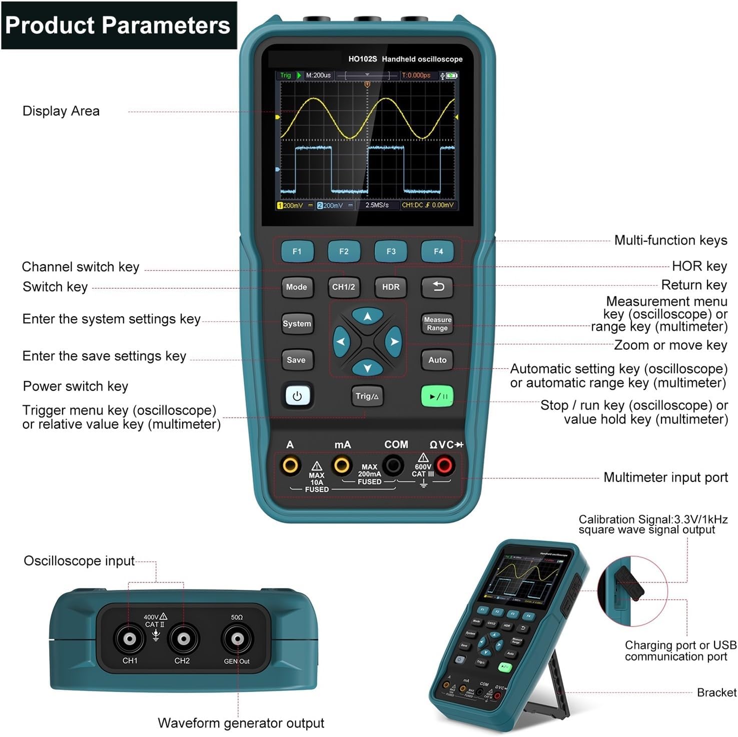
Figure 1: Front and side view of the HO102-100M showing display area, multi-function keys, input ports, and controls. Key labels include F1-F4, Mode, CH1/2, HDR, System, Save, Measure Range, Auto, Power, Trig/Δ, Run/Stop, Multimeter input port, Oscilloscope input (CH1, CH2), GEN Out, Charging port, and Bracket.
- Display Area: Shows waveforms, measurement data, and menu options.
- F1-F4 Keys: Context-sensitive function keys, their labels appear on the screen.
- Mode Key: Switches between different operating modes (Oscilloscope, Multimeter, Waveform Generator).
- CH1/2 Key: Channel switch key for oscilloscope.
- HDR Key: Return key.
- System Key: Enters system settings.
- Save Key: Enters save settings.
- Measure Range Key: Measurement menu key (oscilloscope) or range key (multimeter).
- Auto Key: Automatic setting key (oscilloscope) or automatic range key (multimeter).
- Power Key: Turns the device on/off.
- Trig/Δ Key: Trigger menu key (oscilloscope) or relative value key (multimeter).
- Run/Stop Key (Play/Pause icon): Stops/runs waveform acquisition (oscilloscope) or value hold key (multimeter).
- Navigation Keys (Up/Down/Left/Right/Center): Used for menu navigation and parameter adjustment.
- Multimeter Input Port (A, mA, COM, VΩC+): For multimeter measurements.
- Oscilloscope Input (CH1, CH2): BNC connectors for oscilloscope probes.
- GEN Out: Output for the waveform generator.
- Charging Port / USB Communication Port (Type-C): For charging and PC connection.
- Bracket: Integrated kickstand for desktop use.

Figure 2: The HO102-100M features a 3.5-inch HD LED display and compact dimensions (approximately 10cm x 20cm x 3.5cm). It highlights one-click storage, automatic measurement, dual channel +100MHz bandwidth, and a sample rate of 250MSa/s (Single CH) / 125MSa/s (Dual CH).
4. Setup
4.1 Initial Charging
Before first use, fully charge the device using the provided Type-C USB cable and a compatible power adapter. The charging port is located on the side of the unit.
4.2 Powering On/Off
Press and hold the Power button to turn the device on or off.
4.3 Connecting Probes and Leads
- Oscilloscope Probes: Connect BNC oscilloscope probes to the CH1 or CH2 input ports. Ensure a secure connection.
- Multimeter Leads: Connect multimeter test leads to the appropriate input ports (A, mA, COM, VΩC+) based on the measurement type.
- Waveform Generator Output: Connect a BNC cable to the GEN Out port for waveform output.
5. Operating Instructions
5.1 General Navigation
Use the central navigation keys (Up, Down, Left, Right, Center) to navigate menus, adjust parameters, and confirm selections. The HDR key typically acts as a return or back button.
5.2 Oscilloscope Mode
- Press the Mode button until the oscilloscope interface is displayed.
- Use the CH1/2 button to select the desired input channel.
- Connect the oscilloscope probe to the circuit under test.
- Press the Auto button for automatic waveform display and scaling.
- Adjust vertical sensitivity (Volts/Div) and horizontal time base (Time/Div) using the navigation keys or dedicated function keys (F1-F4, if labeled).
- Use the Trig/Δ button to access trigger settings (e.g., edge, level, mode).
- Press the Measure Range button to display automatic measurements (e.g., Vpp, Vmax, Freq).
- The Run/Stop button (play/pause icon) pauses or resumes waveform acquisition.
5.3 Multimeter Mode
- Press the Mode button until the multimeter interface is displayed.
- Connect the multimeter test leads to the appropriate input jacks for the desired measurement (Voltage, Current, Resistance, Capacitance, Diode, Continuity).
- Use the Measure Range button to cycle through measurement types or ranges, or use the Auto button for auto-ranging.
- The display will show the measurement value.
- Press the Run/Stop button (play/pause icon) to hold the current reading.
5.4 Waveform Generator
- Press the Mode button until the waveform generator interface is displayed.
- Connect a BNC cable from the GEN Out port to the input of the device you wish to test.
- Use the navigation keys and function buttons to select the desired waveform type (e.g., sine, square, triangle), frequency, and amplitude.
- Confirm settings to output the waveform.
5.5 Data Storage and PC Connection
- One-Click Storage: Use the Save button to quickly store waveform data or measurement results.
- PC Connection: Connect the device to a computer using the Type-C USB cable. This allows for data transfer and potentially real-time monitoring with compatible software (software not included, check manufacturer's website for availability).

Figure 3: The HO102-100M in various applications, including PC connection via Type-C, charging, electronic repair, and use in research and education settings.
6. Maintenance
- Cleaning: Clean the instrument's casing with a soft, damp cloth. Do not use abrasive cleaners or solvents.
- Storage: Store the device in a cool, dry place away from direct sunlight and extreme temperatures.
- Battery Care: Although the battery is not demountable, ensure regular charging to maintain battery health. Avoid fully discharging the battery for extended periods.
- Probe Inspection: Regularly inspect test leads and probes for any signs of wear or damage. Replace them if necessary to ensure accurate and safe measurements.
7. Troubleshooting
| Problem | Possible Cause | Solution |
|---|---|---|
| Device does not power on. | Low battery or power button not pressed correctly. | Charge the device. Press and hold the power button firmly for a few seconds. |
| No waveform displayed in oscilloscope mode. | Probe not connected, incorrect input settings, or no signal. | Check probe connection. Press Auto button. Verify signal source. Adjust vertical/horizontal scales. |
| Multimeter readings are incorrect or unstable. | Incorrect lead connection, wrong measurement range, or faulty leads. | Ensure leads are in correct ports. Use Auto range or manually select appropriate range. Inspect and replace leads if damaged. |
| Device freezes or becomes unresponsive. | Software glitch or temporary error. | Perform a soft reset by holding the power button until the device turns off, then restart. If issue persists, contact support. |
8. Specifications
| Parameter | Value |
|---|---|
| Model Number | HO102-100M |
| Digital Channels | 2 |
| Bandwidth | 100MHz |
| Real Time Sampling Rate | 250MSa/s (Single CH), 125MSa/s (Dual CH) |
| Max Waveform Capture Rate | 1,000,000wfm/s |
| Record Length | 8K |
| Display Size | 3.5 Inches |
| Display Resolution | 320*240 Pixels |
| Display Type | TFT True Color LED |
| Battery | Non-demountable |
| Connectivity | USB Type-C |
| DIY Supplies Category | ELECTRICAL |
9. Warranty and Support
For warranty information and technical support, please refer to the documentation provided with your purchase or contact the manufacturer directly. Keep your purchase receipt as proof of purchase.